I’m wanting to implement Jung Regulator for a high voltage power Supply, and I’ve been doing a lot of reading, I also understand that Audio Research Uses the Jung Regulator in several of their power supplies, but I’m trying To find the right Op amp, I’ve looked at the OPA134, and the NE5534, and I’ve read that Walt Jung was favored toward the AD817, it has a high slew rate But not sure how good it would work in this instance.
Any recommendations or criticisms from those smarter than
I am.
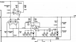
Below is one example from the REF 2 line stage.
Any recommendations or criticisms from those smarter than
I am.
Below is one example from the REF 2 line stage.
Attachments
Last edited:
Not sure what your application is yet or how much output voltage or current capacity you need. In any event I don't have a lot of input as I've never built this power supply, but maybe if you provide a little more info someone will be able to help.
I’m wanting to implement Jung Regulator for a high voltage power Supply, and I’ve been doing a lot of reading, I also understand that Audio Research Uses the Jung Regulator in several of their power supplies, but I’m trying To find the right Op amp, I’ve looked at the OPA134, and the NE5534, and I’ve read that Walt Jung was favored toward the AD817, it has a high slew rate But not sure how good it would work in this instance.
Any recommendations or criticisms from those smarter than
I am.
Below is one example from the REF 2 line stage.
As you see, there are simply no-one smarter than you.
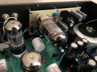
I see three vacuum tubes and, as I have never designed anything with vacuum tubes, I'm a priory lost.
If we can design you a HV power supply/regulator with semiconductors, let us know.
Not sure what your application is yet or how much output voltage or current capacity you need. In any event I don't have a lot of input as I've never built this power supply, but maybe if you provide a little more info someone will be able to help.
apologies for not being more thorough, this will be used in a Full function preamp, my B+ will be around 250VDC and a current demand of Around 40mA. I’m thinking of using a precision Zener(2% tolerance)for reference, maybe power the error amp from the unregulated side?
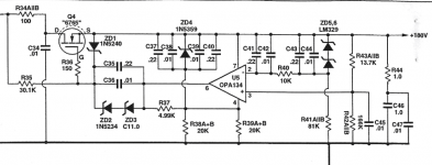
I made a couple of versions, the output voltage is 285V, I use them in my amplifier and DAC. For me the best HV regulator I've tried. The Op amp is NE5534, I tried AD825 but only in LTspice and got worse results than with the NE5534.
Attachments
As you see, there are simply no-one smarter than you.
I see three vacuum tubes and, as I have never designed anything with vacuum tubes, I'm a priory lost.
If we can design you a HV power supply/regulator with semiconductors, let us know.
Not afraid of SS, I have some IRF820’s on hand for series pass element,,
But will I need to float the error amp, if I use a MOSFET?
I made a couple of versions, the output voltage is 285V, I use them in my amplifier and DAC. For me the best HV regulator I've tried. The Op amp is NE5534, I tried AD825 but only in LTspice and got worse results than with the NE5534.
Nice build!!! The 825 and 817’s are good chips! I think there skew rates are
Too fast, if I understand correctly.
What did you use for the pass device?
Not afraid of SS, I have some IRF820’s on hand for series pass element,,
But will I need to float the error amp, if I use a MOSFET?
I feel much more confident with the FET regulator you show. No, I see no need to "float" the error amplifier. The speed of the op-amp is rarely so critical in a linear regulator feedback. You need 180V at the output? How many mAs? Do you have a heavily varying load? What is an acceptable level of ripple? What is your (input) voltage before the regulator?
If I do the tube pass device, the input voltage would be about 400VDC To allow for the drop across the tube, at least 100V or more. The picture was Just an example of the design, there will be some differences. I’m looking at no more than 500uV of ripple. The load will be pretty consistent.
Nice build!!! The 825 and 817’s are good chips! I think there skew rates are
Too fast, if I understand correctly.
What did you use for the pass device?
This is a scheme I used, I added a simple CCS instead of R41. The MOSFET must have Ciss as low as possible.
I think the problem with the AD825 is that it is a JFET op amp and has a high slew rate
Attachments
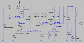
Yes, the high slew rate does present a problem with this application. The DN2540 as a CCS is a great replacement for the simple resistor, much better Performance.
With a rather stable current consumption at the output, and in particular with a ripple as low as 500uV(!), you should consider a shunt regulator - at least in part. They normally have the best regulation/noise performance.
400Vdc input.
Output voltage 250Vdc?
Output current 40mA?
500uV is really low and may be difficult with component noise alone. I doubt you can rely on simulation/calculation of noise at that level.
400Vdc input.
Output voltage 250Vdc?
Output current 40mA?
500uV is really low and may be difficult with component noise alone. I doubt you can rely on simulation/calculation of noise at that level.
Then, I will propose a pre-regulator reducing the input voltage to 300-350V and removing the bulk of the input ripple. From there a high quality drop resistor down to the output and the shunt-regulator. Good foil capacitors at the output.
I once made a 2K4V supply with a ripple of a couple of mV. Measuring the ripple was very difficult. Measuring 500uV on 250V will not be an easy task either.
I once made a 2K4V supply with a ripple of a couple of mV. Measuring the ripple was very difficult. Measuring 500uV on 250V will not be an easy task either.
I tried some popular shunt regulators presented at diyaudio. Some analyzes and measurements I did not work because i have no equipment for that, only 60Mhz scope where shunt and serial reg. look very similar with several mV ripples. But the most important instrument, my ears, say that the serial reg. (from my earlier post) is better than the shunt reg. Shunt reg. is excellent for digital circuits, but for analog circuits (especially tubes) in my experience I prefer this serial reg.
My worry is the 500uV ripple and my experience relates to scientific instruments. I have not been listening to the difference. I was not sure of the use because 500uV ripple, as requested, is lower than what I would expect for audio circuits. If it is for vacuum-tube use, was it practically possible to achieve 500uV ripple in the days where vacuum tubes were common?
If 500uV is really needed, my experience is that a shunt regulator is the best candidate for such performance. A clear disadvantage of the shunt-regulator is its limited operational range. Is the load current varying outside of some 50% (min. consumption to max. consumption) the shunt regulator is not suited.
If 500uV is really needed, my experience is that a shunt regulator is the best candidate for such performance. A clear disadvantage of the shunt-regulator is its limited operational range. Is the load current varying outside of some 50% (min. consumption to max. consumption) the shunt regulator is not suited.
Even 1mV is a very exceptable figure, this is still below audibility, I may just stick with the Maida designs for all my final projects. It is a great performer, and
Low parts count.
Low parts count.
Hi denny9167,
Hope I'm not too late jumping in, but I'd sure like to add '2' to the low parts count:
A couple of 1N4148's (or whatever is on hand) back to back across the op amp inputs, pins 2 and 3, would give me less worry. Remember, some of these designs, before they're running and stable, may see some pretty high voltages on on the feedback divider. Filaments don't always warm up at the same rate.
It'd probably be worth adding another pair to constrain the feedback input to a diode drop above or below supply rails, too.
Just a thought.
Best Regards,
Rick
- Home
- Amplifiers
- Power Supplies
- High Voltage Jung Regulator