We experience a high failure rate, up to 30%, on the PAM8610 breakout board. The faults are different. No speaker output, distorted output, High current consumption (>500mA), etc.
Anybody has the same experience? Do we do something wrong or is it a low quality item?
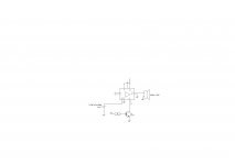
The attached diagram shows what we do. Confusing for us is the following: Setting the SW to 0, Fade is working perfect, If we open the SW, we measure the full supply voltage on the pin marked SW. The data sheet specifies that the absolute maximum rating for FADE is 0-6V. I have attached the data sheet.
Anybody has the same experience? Do we do something wrong or is it a low quality item?
The attached diagram shows what we do. Confusing for us is the following: Setting the SW to 0, Fade is working perfect, If we open the SW, we measure the full supply voltage on the pin marked SW. The data sheet specifies that the absolute maximum rating for FADE is 0-6V. I have attached the data sheet.
Attachments
Pam 8610 has a bridged output, which means floating, connected to speaker terminals but NOT to ground.
You are shorting one of them to ground and applying half DC supply voltage to speaker.
No surprise amp overheats, distorts and pulls HIGH current continuously.
Connect it as datasheet clearly suggests.
You are shorting one of them to ground and applying half DC supply voltage to speaker.
No surprise amp overheats, distorts and pulls HIGH current continuously.
Connect it as datasheet clearly suggests.

I hope the schematic you included was intentionally incomplete -- you're missing quite a few necessary capacitors, particularly those for bootstrap, input, COSC and VCLAMP .
There's a lot of great info on pages 9 through 12 of the datasheet PDF.
Also, in general I wouldn't leave an input floating on a CMOS part. If you aren't using the Left channel, something will need to be done with those inputs.
Cheers
There's a lot of great info on pages 9 through 12 of the datasheet PDF.
Also, in general I wouldn't leave an input floating on a CMOS part. If you aren't using the Left channel, something will need to be done with those inputs.
Cheers
Last edited:
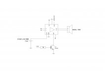
Thank you very much for your replies. My mistake, the diagram is wrong. We did not connect the speaker to GRND but to the the ROUT of the breakout board. I have attached a picture of the board we use. A new and now correct diagram is also attached.
As I said, we used 50 of these amplifier boards. 38 worked perfectly but 12 of them showed different faults. As I do not believe that the product is that bad, I am afraid that we made a mistake somewhere. Leaving the L Input open could be one of the problems. On page 15 of the data sheet, the differential input is explained. Is my understanding correct that we should connect the LIN to ground by a capacitor of 1uF?
As I said, we used 50 of these amplifier boards. 38 worked perfectly but 12 of them showed different faults. As I do not believe that the product is that bad, I am afraid that we made a mistake somewhere. Leaving the L Input open could be one of the problems. On page 15 of the data sheet, the differential input is explained. Is my understanding correct that we should connect the LIN to ground by a capacitor of 1uF?
Attachments
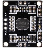
Beautiful board! But it shows 26 supporting parts, and no BC547. Others here may be able to help without a complete schematic, but I cannot. Perhaps your management regards it as proprietary? Sorry about that. 😕
The specs PDF offers additional challenges.
Maybe it's just me, but I would personally not expect any IC that measures 6x6 millimeters, regardless of technology, to drive a 4 ohm load with 10+ watts -- and live to tell about it.
As to the unused LIN's, I found no info about managing an unused signal input. It does say that a single-ended source should be applied to IN-, with the (no-signal) IN+ receiving its AC ground from the other end of the source cable. Just guessing, but, maybe try the 1uF to ground on the IN+ input, then with another 1uF or 0,47uF from it to the IN- for the latter's AC ground. And use low leakage types if at all possible.
If you do have a COSC fitted, it too should be a low-leakage, high-quality type with good stability over temperature.
Cheers
*1) may be different than yours: https://www.mouser.com/datasheet/2/115/DIOD_S_A0011483262_1-2512937.pdf
The specs PDF offers additional challenges.
- I've searched and scanned the entire thing (*1) and there's no "Table 1". Testing would be required to determine the device's gain over a 107 dB range
- (I've searched and scanned the entire thing) and find no instance of an "SW" signal (as marked on your board and "schematic"); what is it? Leaving it floating when the BC547 turns off may not be something the IC likes either.
- the Diodes Inc version of the PDF is plastered with giant diagonal "Not Recommended For New Designs" rubber-stamp-imprints; Mouser shows ~1700 in stock, but what distributors have on hand may be the end of its availability
- the recommended replacement device (PAM8006) does not have the DC-controlled-32-step-Volume function
- there are a surprising number of grammar errors, some of which render the sentence ambiguous
- only one set of 6 graphs makes any reference to driving 4 ohms; there is no mention of it in the text
Maybe it's just me, but I would personally not expect any IC that measures 6x6 millimeters, regardless of technology, to drive a 4 ohm load with 10+ watts -- and live to tell about it.
As to the unused LIN's, I found no info about managing an unused signal input. It does say that a single-ended source should be applied to IN-, with the (no-signal) IN+ receiving its AC ground from the other end of the source cable. Just guessing, but, maybe try the 1uF to ground on the IN+ input, then with another 1uF or 0,47uF from it to the IN- for the latter's AC ground. And use low leakage types if at all possible.
If you do have a COSC fitted, it too should be a low-leakage, high-quality type with good stability over temperature.
Cheers
*1) may be different than yours: https://www.mouser.com/datasheet/2/115/DIOD_S_A0011483262_1-2512937.pdf
Last edited:
Dear Rick
Tank you very much for the detailed answer. Just to clarify. We do not make the breakeout board with the PAM8610. We buy these units from different suppliers. The internet is full of resellers offering it. We currently use them to make 50 units of a wireless speaker. This is to do a proof of concept. Therefore we bought 50 pcs of these breakeout boards. 33 worked perfectly. Low power consumption, good sound. 13 of the boards showed different faults.
This is why I was wondering if we made a mistake on our side or if the quality of these boards are questionable.
The SW input on the breakeout board is the fade function. Normally the supply voltage is present at this input. To activate the Fade function, we pull the SW input to zero by the BC547.
- Home
- Amplifiers
- Chip Amps
- High failure Rate of PAM8610 Board