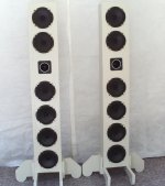
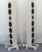
This is a speaker system that I completed earlier this year.
Goal: A line array with efficiency of about 100dB 1W/1M not weighing more than about 50 pounds and is not too large so that it can be easily set-up and stored. The speaker system is intended to be driven by a class D amp powered by a 12V rechargeable battery rated 12AH.
A. One horn tweeter and six 5.25 inch woofers. This is a two-way closed-box system with a crossover frequency of 2 kHz.
1. The width of the enclosure equals 7.75 inches. For this width and where Fstep equals the baffle step frequency,
Fstep = (4560 in./ 7.75 in.) = 588 Hz
Thus the tweeter functioning at freq. > 2 kHz has efficiency in its operating frequency range equal to its rated efficiency of 100 dB 1W/1M.
2. Efficiency of each of the six woofers is specified as 89 dB 1W/1M. As a result of driving the six woofers together,
efficiency gain = 10*Log(6) = 7.8 dB
(Thanks to James R. Griffin, PH.D for this equation)
Thus efficiency of the six woofers driven together equals 97 dB 1W/1M. -only 3 dB away from efficiency of the tweeter!
B. Line Array
1. Center-to-center spacing of the woofers mostly equals 6.5 inches. This means that the woofers can function as a line array for freq. < 2 kHz. This is given that wavelength at 2 kHz equals 6.5 inches. Two of the woofers and the tweeter are positioned on the baffle in the D'Appolito MTM arrangement.
2. For the line array, intensity decreases at 3 dB and 6 dB per doubling of distance for respectively near and far field reproduction. Where d equals the distance at which the transition from near to far field reproduction occurs or the critical distance,
d = 1.5*f*H^2 (Griffin)
where f= frequency in kHz and H is the height of the array in meters.
3. Listener distance from the array is made equal to 2 meters to facilitate the listener being in the near field reproduction by the array as much as possible. Because I wanted the speaker to be easily moved, I limited the number of woofers to six, and the resultant height of the array between the radiation axes of the top and bottom woofers equals 1 meter. Given critical distance d equals 2 meters, height of the array equals 1 meter, and solving for frequency in the previous equation,
f = d/(1.5*H^2)
= 2/(1.5*1)
=1.3 kHz
This means that the listener is in the near field reproduction of the line array where freq. > 1.3 kHz. This is less than an octave below the crossover frequency of 2 kHz.
C. Equalization. I need to do some more thinking about how I came up with the equalization that was implemented.
Attachments

Last edited:

In trying to figure out what would be the correct equalization for my speaker, I think I know how to correctly determine that, but I'm not absolutely certain.
See what you think. Below is a pdf that I have been referring to.
www.avsforum.com/attachments/griffin-line-array-pdf.3124827
RE: "normal" propagation of a cone speaker driver versus propagation of a multiple of the driver in a line array
Correct me if I'm wrong, but I think that the specified power sensitivity of a speaker driver applies to normal (spherical) propagation of the driver into half-space.
So if for example the power sensitivity of each driver equals 90 dB 1W/1M and I make a line array composed of ten of these drivers, then (following what is given on p.17 of the paper by Griffin),
efficiency gain = 10*log(number of drivers driven)
efficiency gain = 10 * log(10)
efficiency gain = 10 dB
From this I would conclude (correctly?) that if the combined ten drivers are propagating normally (not as a line array), then at 1 meter distant from the speaker system and 1 Watt used SPL equals 100 dB.
On the other hand, if Griffin's critical distance (p. 4) is > 1 meter and thus the combined drivers are functioning as a line array, then again taken at 1 meter distant from the speaker system and 1 Watt used SPL equals 103 dB.
Thanks for letting me know if you agree or not.
-Pete
D
Deleted member 375592
I also use 6 woofers, 5.25" each, 91dB/W@1m, spaced 1'. This is how it works depending on the distance, in my living room, from 100cm to 400cm:

It does not work anywhere nice with a single tweeter (or horn) because the tweeter intensity falls -6dB per distance doubling (here I used a focused array).

So I used a 200mm tall ribbon. It is better ... but it looks like I need 2 of those.

This family of curves looks more equalizable. Otherwise, the tonality would fluctuate greatly depending on your position (including the ear height). However, I need to play more with the drivers' positioning to make it more ... "coherent". it is not as straightforward as it looks.
BTW, I do not know who it is Griffin but if you connect the drivers serially, R-> R*N, for the same output in dB / voltage. P=V^2/(R*N) = P1/N (P1=V^2/R), so it looks like efficiency raises as 20*dB(N)
It does not work anywhere nice with a single tweeter (or horn) because the tweeter intensity falls -6dB per distance doubling (here I used a focused array).
So I used a 200mm tall ribbon. It is better ... but it looks like I need 2 of those.
This family of curves looks more equalizable. Otherwise, the tonality would fluctuate greatly depending on your position (including the ear height). However, I need to play more with the drivers' positioning to make it more ... "coherent". it is not as straightforward as it looks.
BTW, I do not know who it is Griffin but if you connect the drivers serially, R-> R*N, for the same output in dB / voltage. P=V^2/(R*N) = P1/N (P1=V^2/R), so it looks like efficiency raises as 20*dB(N)
Where connecting two identical drivers in series or parallel, power sensitivity increases by 3 dB. See Q21 at
www.linkwitzlab.com/faq.htm
Griffin's equation, referring to power sensitivity,
efficiency gain = 10*log (number of drivers) = 10*log (2) =3 dB
So Griffin's equation agrees with Linkwitz's analysis. Consider say 4 drivers connected in parallel and treat each of two pairs of drivers as a single driver with power sensitivity increased by 3 dB. Then apply Linkwitz's analysis again to the two contrived drivers and get an overall power sensitivity gain of 6 dB.
efficiency gain = 10*log (number of drivers) = 10*log (4) = 6 dB
I couldn't follow your argument about Griffin's equation at the end of your post.
Last edited:
As Pete has proposed using a horn tweeter with his 6 midrange drivers for his line array. His mids will follow a 3 dB fall off per doubling of distance while the horn tweeter will follow a 6 dB fall off. Essentially, Pete could EQ so that at the listening position he would equate the sound from the two sets of drivers. While it would be better to have a line of tweeters (I've used ribbon or planar tweeters for several designs) to universally perfect the sound within a listening area. I once built and used a line array design with multiple midranges and a single 8 inch long ribbon driver. This design was impressive but clearly flawed with its sound imbalance at some areas of the room.
You might lookup that 'Griffin' guy's white paper at:
http://www.audioroundtable.com/misc/nflawp.pdf
You might like to read pages 17 and 18 for his approach for computing line array efficiency and sensitivity levels.
Jim
You might lookup that 'Griffin' guy's white paper at:
http://www.audioroundtable.com/misc/nflawp.pdf
You might like to read pages 17 and 18 for his approach for computing line array efficiency and sensitivity levels.
Jim
D
Deleted member 375592
You are right, I made a stupid mistake in taking the logarithm.I couldn't follow your argument about Griffin's equation at the end of your post.
D
Deleted member 375592
Hello Jim,You might lookup that 'Griffin' guy's white paper at:
Yes, I've read your paper a few months back. A good one. I completely forgot the author's name.
BTW, I experimented with near-field beamforming (which I called focused above) arrays which you did not like much, uneven positioning, a variable number of drivers, mixing drivers, and two vertically spaced subwoofers. Let me know if any of these interests you.
Thanks,
Michael
So what you’ve made here isn’t a line array but closer to a line source…..not equal to that either as the driver offset is not symmetrical. I wouldn‘t suggest you attempt to beat it onto performing as such……you’ll wind up with an awful mess in the power response.
My suggestion to you would be to modify the network into a 2.5 framework by adding a first order low pass to the lowest and highest midwoofers. Power response will even out accordingly.
Remember that EQ is a function of phase so shaping response (axial, power, phase) is always going to be detrimental to the clarity of the sound. This is why professional recording engineers choose from many microphones to find the one who’s response curve is desired natively as to not require shaping through EQ which adds phase distortion. If you can implement the same strategy in speaker design, you’ll be way ahead of most.
Last edited:
Michael, yes I am not a fan of concave focused line arrays but I am a big fan of Don Keele's constant beamwidth transducer work. A CBT typically is a convex array unless you segment a straight array and add phase shift (time delay) networks with multiple channels for implementing the time delays. My Modified CBT24 project is a keeper and used daily in my living room. See my CBT project as reported at:
https://www.diyaudio.com/community/threads/my-new-line-array-its-a-modified-cbt24.313352/
My CBT arrays have nearly constant amplitude, beamwidth, and frequency response within my room. The CBTs sound the same 2 inches or 20 feet away from their enclosures in my space. No straight line array chaotic near field radiation stuff or comb lining as you walk around the room. The arrays are five feet high and while I'm 6"3" tall, the sound is excellent either standing or sitting anywhere in the room.
Last edited:
D
Deleted member 375592
Very impressive work!
I am not a big fan of constant directivity / superdirective arrays after working with microphone arrays for remote sensing. I do not know if I am a fan of concave arrays either because I have not finished my arrays yet. 2 of my friends who work on CNC machines promised to provide me with free HDF cabinets within a month or a maximum of two... I am still waiting - but not for long. I have gone through the DSPs available and was deeply disappointed by their amateurishness... but I'll find something workable.
Jim, do you know anything about the rise of the low frequencies in arrays placed in the corner? This is the picture I get quite consistently:

The dark green curve is of one speaker in the corner, at ~85cm high, at 1m. It is somewhat flat over the 80...3000Hz range. The rest are of a concave array at various distances (100...400cm), the same 85 cm high. You can see a strong line source behavior at 2kHz, gradually receding into a more relaxed point source-ness at 250Hz. But then, it again becomes more line-source-like by 100Hz, and there is a gain. This gain is not the room gain per se because the dashed line is taken as the top of the ridge of the normalized wavelet transform (window length ~1/freq). I am quite puzzled. Have you observed anything similar?
Thanks,
Michael
I am not a big fan of constant directivity / superdirective arrays after working with microphone arrays for remote sensing. I do not know if I am a fan of concave arrays either because I have not finished my arrays yet. 2 of my friends who work on CNC machines promised to provide me with free HDF cabinets within a month or a maximum of two... I am still waiting - but not for long. I have gone through the DSPs available and was deeply disappointed by their amateurishness... but I'll find something workable.
Jim, do you know anything about the rise of the low frequencies in arrays placed in the corner? This is the picture I get quite consistently:
The dark green curve is of one speaker in the corner, at ~85cm high, at 1m. It is somewhat flat over the 80...3000Hz range. The rest are of a concave array at various distances (100...400cm), the same 85 cm high. You can see a strong line source behavior at 2kHz, gradually receding into a more relaxed point source-ness at 250Hz. But then, it again becomes more line-source-like by 100Hz, and there is a gain. This gain is not the room gain per se because the dashed line is taken as the top of the ridge of the normalized wavelet transform (window length ~1/freq). I am quite puzzled. Have you observed anything similar?
Thanks,
Michael
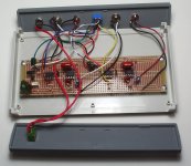
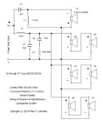
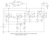
My original thinking in making maximum gain of the shelving low-pass filter including op amp U3B of the equalizer equal to 12 dB was really flawed. See the circuit diagram of my equalizer attached to my first post. Fortunately I deleted it from my first post quickly or else I would be really embarrassed.
So anyway here is the reasoning behind what i think it should be which is 6 dB. The shelving low-pass filter is intended to compensate for my speaker propagating in a flawed manner or incompletely as a line array for frequency < 1,3 kHz.
Where Griffin's critical distance is equal to 2 meters (where my listener sits) or greater, output level of my speaker equals 100 dB at 1 meter distant from the speaker. At 2 meters the level is 97 dB
As Griffin points out in the paper that I provided a link to in my first post, where height of the line array is fixed, then critical distance is directly proportional to frequency.
Where the critical distance is very much less than 1 meter, then output level of my line array equals 97 dB at 1 meter and 91 dB at 2 meters. The difference between SPL at 2 meters (the listener's location) where my speaker propagates as a line source or line array is 6 dB. One of the things that the equalizer is to accomplish is to fill in for the loss of SPL in the frequency range where my speaker functions only partially as a line array.
Thus maximum gain in the bass range of the shelving low-pass filter including op amp U3B of my equalizer should be 6 dB, not 12 dB. I've changed the filter to produce a maximum voltage gain of 2 at 100 Hz. See the attached revised circuit diagram.
The shelving low-pass filter of my equalizer including op amp U3A is for baffle step compensation.
Attachments
Hi Jim,Michael, yes I am not a fan of concave focused line arrays but I am a big fan of Don Keele's constant beamwidth transducer work. A CBT typically is a convex array unless you segment a straight array and add phase shift (time delay) networks with multiple channels for implementing the time delays. My Modified CBT24 project is a keeper and used daily in my living room. See my CBT project as reported at:
https://www.diyaudio.com/community/threads/my-new-line-array-its-a-modified-cbt24.313352/
My CBT arrays have nearly constant amplitude, beamwidth, and frequency response within my room. The CBTs sound the same 2 inches or 20 feet away from their enclosures in my space. No straight line array chaotic near field radiation stuff or comb lining as you walk around the room. The arrays are five feet high and while I'm 6"3" tall, the sound is excellent either standing or sitting anywhere in the room.
Im intrique by your CBT24 project. Was wondering if there is now a better sounding driver than the SB drivers that your using.
Many thanks
Concerning my Modified CBT24 project I haven't really sought a better sounding driver than the SB65 unit. I did try samples of several other small drivers before that project was solidified.
For future CBT projects I've taken a look at the SB Acoustics SB10PGC21-4 (a 3 inch full range driver), the DaytonAudio DMA45-4 (1.5 inch unit), and the Tectonic TEBM35C10-4 (2 inch unit). None of these drivers replace the SB65 in the Modified CBT24 design and all of them cost less than the SB65.
For future CBT projects I've taken a look at the SB Acoustics SB10PGC21-4 (a 3 inch full range driver), the DaytonAudio DMA45-4 (1.5 inch unit), and the Tectonic TEBM35C10-4 (2 inch unit). None of these drivers replace the SB65 in the Modified CBT24 design and all of them cost less than the SB65.
Many thanks Jim, wonder if the Faital Pro 3fe22 will work well as I've
played with a couple of them. Yes the SB65 is rather costly for CBT24 in total. lol
played with a couple of them. Yes the SB65 is rather costly for CBT24 in total. lol
After evaluating a pair of SB65 when I wanted more the China distributor/retailer is out of stock. Maybe I'll downgrade from $30ea to $2ea old-stock something or other.
Sumotan, the Faital Pro 3fe22 is a neo magnet driver which sells for $37.50 each from Parts Express in the US. Even the 3fe25 ferric magnet unit sells for $24.50 each. The Faital units are excellent performers for 3 inch drivers but some DIYers may not like these prices.
Wow didn't notice price Jim cause over my end one could purchase the 3fe22 for around $16 each but
than again multplied by 48 pcs ends up to be a substantial amount just for drivers alone too.
How about Visaton FRS 5X-8 saw a shop selling it for $6.21 ea. Though 2 inch but seems to have nice
response & 86db sensitivity too.
Many thanks again
than again multplied by 48 pcs ends up to be a substantial amount just for drivers alone too.
How about Visaton FRS 5X-8 saw a shop selling it for $6.21 ea. Though 2 inch but seems to have nice
response & 86db sensitivity too.
Many thanks again
His mids will follow a 3 dB fall off per doubling of distance while the horn tweeter will follow a 6 dB fall off.
Actually, every speaker got a near field in which the level drops only by 3dB per double distance. That depends on driver/array dimensions and frequency how far that extends. Also, the array in this configuration is too short to act as an array on the lower end. And the distance is too big to act as an array at higher frequencies too. That results in the near field ending at different lengths, causing the tonality/fr to change with increasing distance. That is not a problem within a certain listening distance but you should be aware of it.
I’ve used that little SB a few times as a mid tweeter and for the $$, it’s very hard to beat IMO.…..it all becomes boutique nonsense with diminished returns. I think some folks over at the fullrange forum even built it into a large horn and where quite giddy over the results.Hi Jim,
Im intrique by your CBT24 project. Was wondering if there is now a better sounding driver than the SB drivers that your using.
Many thanks
- Home
- Loudspeakers
- Multi-Way
- High Efficiency Line Array