I've built a pair of mono 300b single ended amplifiers. They were working just fine but the filament voltage was too low so I invested in a Coleman regulator and that's all fixed now. One of them I rebuilt with the new regulator and works flawlessly. The other has an issue which cropped up after the rebuild. I'm not that experienced so I have a rough idea of what's causing the issue but I'd like to see if my troubleshooting process is correct and what you guys think may be causing this. As of right now I have yet to find the culprit and solve it.
As I power up the amplifier the B+ voltage rises slowly as expected to about ~430V where it's expected then suddenly drops at around ~350V. I knew the only tube capable of drawing so much current to drop the voltage that much had to be the power tube so I checked its bias and it's around ~150V which to my understanding is extremely high (therefore I didn't leave the amp on for more than a few seconds just to get the reading). I checked and the tube was thankfully not red plating and I also check the filament supply to be galvanically isolated from B+ ground. So I believe there's some issue in the biasing circuit, although it's extremely: just a 880R resistor which measures fine and is rated at 50 watts, and a 100uf bypass cap. My first though was a bad cap, but after taking it out of circuit it tests fine (could it be leaky though?).
Another issue I'm facing with this unit is that it makes some scratching noises as it powers up and even after "settling in" (albeit for the few seconds I've kept it powered with high B+).
I believe this may be related to the previous issue or be caused by some (new) cold solder joints. Any tips on finding those out?
I'll try swapping the capacitor for a new quality one if it's deemed to be the only possible cause of the issue.
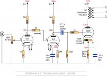
I'll leave the schematic of the signal circuitry if it can be of any help. The PSU has been designed from scratch and it's just a simple CLCRC unregulated.
In the schematic an humpot is used, but now that I use a DC regulated supply I believe it can be removed right? How should I wire the bias without it?
Thank you for your time and I really hope I'll be able to give back to this community one day when I'll have more experience under my belt.
As I power up the amplifier the B+ voltage rises slowly as expected to about ~430V where it's expected then suddenly drops at around ~350V. I knew the only tube capable of drawing so much current to drop the voltage that much had to be the power tube so I checked its bias and it's around ~150V which to my understanding is extremely high (therefore I didn't leave the amp on for more than a few seconds just to get the reading). I checked and the tube was thankfully not red plating and I also check the filament supply to be galvanically isolated from B+ ground. So I believe there's some issue in the biasing circuit, although it's extremely: just a 880R resistor which measures fine and is rated at 50 watts, and a 100uf bypass cap. My first though was a bad cap, but after taking it out of circuit it tests fine (could it be leaky though?).
Another issue I'm facing with this unit is that it makes some scratching noises as it powers up and even after "settling in" (albeit for the few seconds I've kept it powered with high B+).
I believe this may be related to the previous issue or be caused by some (new) cold solder joints. Any tips on finding those out?
I'll try swapping the capacitor for a new quality one if it's deemed to be the only possible cause of the issue.
I'll leave the schematic of the signal circuitry if it can be of any help. The PSU has been designed from scratch and it's just a simple CLCRC unregulated.
In the schematic an humpot is used, but now that I use a DC regulated supply I believe it can be removed right? How should I wire the bias without it?
Thank you for your time and I really hope I'll be able to give back to this community one day when I'll have more experience under my belt.
Attachments
Hello Luca,
A possible problem is the coupling capacitor 0,22µF at the 300B grid. If you have used the Jupiter caps, these have a paper/wax dielectric, and may suffer from leakage. Paper-in-oil types can have the same problem. If you have some normal industrial 100nF or 220nF high voltage capacitors, you can try them.
A possible problem is the coupling capacitor 0,22µF at the 300B grid. If you have used the Jupiter caps, these have a paper/wax dielectric, and may suffer from leakage. Paper-in-oil types can have the same problem. If you have some normal industrial 100nF or 220nF high voltage capacitors, you can try them.
With my regulators for the 300B filament, please remove the humpot, and connect the cathode bias resistor to the NEGATIVE side of the filament, for the V9 Regulator.
I deviated from the schematic here and used some Solen MKP 22nF 630V for coupling the driver to the 300b, so I don' think that's the case.Hello Luca,
A possible problem is the coupling capacitor 0,22µF at the 300B grid. If you have used the Jupiter caps, these have a paper/wax dielectric, and may suffer from leakage. Paper-in-oil types can have the same problem. If you have some normal industrial 100nF or 220nF high voltage capacitors, you can try them.
Thank you for the wiring guidance, I'll be sure to follow it. BTW your regulators work flawlessly and the ripple is below my measurement equipment which is awesome.With my regulators for the 300B filament, please remove the humpot, and connect the cathode bias resistor to the NEGATIVE side of the filament, for the V9 Regulator.
UPDATE: I have now connected the bias circuit to the negative pin of the filament supply. The voltage still rises incredibly high but I can hear a sine wave hum (can't really tell the frequency) along with the previously reported scratching/pops. I could find the frequency with my o-scope but I'm afraid keeping the amp powered in this condition might damage it. I'll wait for some suggestion from you more experienced people.
Remove the coupling capacitors.
Are you sure, that 300B grid leak resistor 200k is tied to grid (via 1k grid stopper)?
Try to measure 300B anode, and cathode resistor voltage.
If the later not to close to expected 69V (about 78mA cathode current), your tube is run away (too much voltage)... or R.C. power supply is earthed (too small voltage).
If you have the oscilloscope, you can measure the grid voltage, as the amp starts up.
If the B+ is slow-rising , the grid voltage should not be above ground.
But if the grid voltage is high, you can remove the grid coupling cap, as euro21 says.
If the grid voltage is still too high, it may be that the 300B grid is leaking current, because of gas (bad vacuum in 300B).
If the B+ is slow-rising , the grid voltage should not be above ground.
But if the grid voltage is high, you can remove the grid coupling cap, as euro21 says.
If the grid voltage is still too high, it may be that the 300B grid is leaking current, because of gas (bad vacuum in 300B).
Checked the grid leak and grid stopper resistors and can confirm they are connected as shown in the schematic.Remove the coupling capacitors.
Are you sure, that 300B grid leak resistor 200k is tied to grid (via 1k grid stopper)?
Try to measure 300B anode, and cathode resistor voltage.
If the later not to close to expected 69V (about 78mA cathode current), your tube is run away (too much voltage)... or R.C. power supply is earthed (too small voltage).
The anode of the 300b is at 350V or less, just slightly below the B+ that's feeding the OPT, which is to be expected at no signal input (right?). Still even with no signal I can hear the scratching on my test speaker.
The cathode resistor voltage is as initially reported 150-200v which is waaaay out. This makes it look like the tube's faulty. That said I have tried with a known working tube and the same behavior happens, the only difference being that this tube allows the voltage to rise to the expected 420V for maybe a second and then drops to 350V.
I don't think the Coleman regulator is shorted to ground as that was one of the first things I checked: the positive line shows no continuity, while the negative line shows 880R to ground which is to be expected from the cathode resistor.
I will attempt the check Rod suggested with my scope before removing the coupling cap.
So I've put my scope (AC coupled) on the grid as the amplifier powers on. The B+ is fed by a vacuum tube rectifier so it rises slowly: in these few seconds the voltage on the grid goes up to 50v above ground. I don't really know if this is considered "too much".If you have the oscilloscope, you can measure the grid voltage, as the amp starts up.
If the B+ is slow-rising , the grid voltage should not be above ground.
But if the grid voltage is high, you can remove the grid coupling cap, as euro21 says.
If the grid voltage is still too high, it may be that the 300B grid is leaking current, because of gas (bad vacuum in 300B).
The thing is, I have another identical circuit built that's working, and I can confirm the tube's not leaky (works fine in the other amp with 71V across the cathode resistor) and the coupling cap is not a problem (it's present in the other amp), so it has to be an error in the wiring or some bad component. You think the coupling cap could be bad?
EDIT: one more thing I tried was biasing the tube with just the 880R resistor, which should yield lower bias. It didn't prevent the cathode resistor voltage from shooting up as usual but it did delay it a bit, therefore I could see the B+ reaching its expected voltage before plummeting as the bias increased.
Last edited:
If the rise time of B+ is a few seconds ( longer than the time constant of the 220nF - 220k) the grid voltage should not rise by anything like 50V.
Does the 220k measure 220k?
Either the 220k is high - or not connected to the grid, or there is some current feeding in from somewhere.
If you disconnect one side of the 220nF, does the 50V still appear?
Does the 220k measure 220k?
Either the 220k is high - or not connected to the grid, or there is some current feeding in from somewhere.
If you disconnect one side of the 220nF, does the 50V still appear?
Bias -usually- only depends of voltage on cathode resistor (if grid grounded via grid leak resistor), so with or without decoupling capacitor remains the same.one more thing I tried was biasing the tube with just the 880R resistor, which should yield lower bias.
If the cathode decoupling capacitor is failed, the bias voltage (relative to grounded grid) may decreasing, so anode current goes up.
Yes double checked that.Is the cathode decoupling capacitor polarity correct?
The 220k measures 117k which I guess it's within margins.If the rise time of B+ is a few seconds ( longer than the time constant of the 220nF - 220k) the grid voltage should not rise by anything like 50V.
Does the 220k measure 220k?
Either the 220k is high - or not connected to the grid, or there is some current feeding in from somewhere.
If you disconnect one side of the 220nF, does the 50V still appear?
Disconnecting the 220nF capacitor from the anode of the driver removes the voltage on the grid of the 300b and the bias is now within reason at 72V.
So this solves the issue, but of course I don't have any signal coming trough now. Does this mean I have a bad coupling cap? The amplifier was working before (only with a too low filament voltage) and the cap tests at 220nF precisely. What else could be causing this?
Yes.Does this mean I have a bad coupling cap?
Some manufacturer's capacitor intolerant to high temperature within tube amplifier.
Some years ago very famous -and very very pricey- capacitors tend to go bad tendentiously.
The cap should have zero DC leakage current. So if you have another capacitor - any value 100n - 330n you could try it.
if it still fails, and you have another resistor 100k - 270k you can try it.
if it still fails, and you have another resistor 100k - 270k you can try it.
Yeah so just to make sure I get this right, the cap is supposed to stop the DC feeding the driver plate from getting to the 300b grid and only let the singal through. Here it's clearly not working as I was seeing DC voltage with no signal on the grid of the power tube.
Thank you very much for the troubleshooting process, the advice received from the both of you has been priceless. Tomorrow I'll try to swap the capacitor for a known working one and we'll see how it goes.
Thank you very much for the troubleshooting process, the advice received from the both of you has been priceless. Tomorrow I'll try to swap the capacitor for a known working one and we'll see how it goes.
- Home
- Amplifiers
- Tubes / Valves
- High bias, low B+ voltage DHT