i watched a friend break the crossover switch with a screwdriver.
i told him not to worry about the value of the amplifier being ruined because the switch is cheap to replace.
but
i dont know what type of switch it is for me to go out there and get a replacement.
looking at the pins, it looks like this..
::: :
doing a visual reference, i seen some double pole - triple throw switches with the same pins.
i dont want to use pin layout only.
the switch is for the crossover, selectable between high-pass|full|low-pass
i thought it would be easy to match up the pins.. but then i learned about on-on-on and on-off-on positions.
i dont want to get the wrong switch and see something break when he flips the switch.
(i also dont know how much voltage the switch has to work with)
when i went to google to find a tutorial on how to test a switch to determine what kind it was, it came up with empty offtopic posts.
i tried youtube for a tutorial and again didnt find anything.
so then i went back to the search engine and tried to find something that talks about how a switch with those pins work.
all i came up with was one of two things:
the : can get a seperate wire on each side and the switch makes contact between them.
or
the : can get one wire and the switch makes contact between different : pins.
i'm willing to learn how to test the switch, but i've only got one multimeter and i dont know if the test requires more than one meter.
The attached diagram shows the internal connections for a 3 position switch similar to yours. The attached switch has 4 circuits instead of the 2 circuits that your has.
In each of the 3 positions, the shorting bar shorts the two contacts indicated in the drawing.
I've never seen a switch like this that had a position that had no connection between at least 2 of the contacts (no 'off' position unless the circuit board has no connections to it).
In each of the 3 positions, the shorting bar shorts the two contacts indicated in the drawing.
I've never seen a switch like this that had a position that had no connection between at least 2 of the contacts (no 'off' position unless the circuit board has no connections to it).
Attachments

the picture isnt self-explanitory.
i see there is a single number for each pin on top and on the bottom.
and it would make sense
1 and 5
2 and 6
3 and 7
4 and 8
but
1 and 2
2 and 3
3 and 4
all of those being connected tells me there is more going on than a simple on and off for a circuit.
the combination of two circuits is always happening.
i dont know what the details of the circuits are that the switch is for.
i dont know if the contacts inside are horizontal like in the picture or verticle.
if i take the switch out and make use of whatever slider is left to get resistance readings for each pin top to bottom, and then each pin left to right.. that still doesnt tell me which one i need to pick from the list.
maybe i will jst take it out and find out what pins do what and then call or email one of the companies selling switches and ask them what type of switch is laying there in front of me.
they cant have any money if i dont know which one i need.. LOL
i seen this forum thread:
Rapiring slide switch for crossover switch - DIYMA Car Audio Forum
the picture shows two broken switches.
each switch has this inside,
_ __ _ _
_ __ _ _
the below pictures show what i can gather from those pieces of contacts (its obvious those switches are triple-throw)


the suggested replacement switches show the same pin layout as the switch i'm looking to replace.
but
i'm not seeing how its a double-pole or triple-pole.
and i'm assuming each pin does the same exact thing on the top as it does on the bottom, to help from static or if one pin wears out and stops making contact?
Rapiring slide switch for crossover switch - DIYMA Car Audio Forum
the picture shows two broken switches.
each switch has this inside,
_ __ _ _
_ __ _ _
the below pictures show what i can gather from those pieces of contacts (its obvious those switches are triple-throw)
the suggested replacement switches show the same pin layout as the switch i'm looking to replace.
but
i'm not seeing how its a double-pole or triple-pole.
and i'm assuming each pin does the same exact thing on the top as it does on the bottom, to help from static or if one pin wears out and stops making contact?
this is the only way i can rationalize a double throw switch when each pin on the top and bottom is used the same as the pin below:
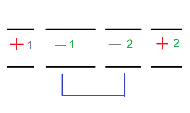
if the top pin was positive and the bottom pin was negative, then that means more than one 'set' or 'circuit' would come into contact with eachother.
that is about as bad as a positive and negative touching at a switch that is ment to simply break (open) or close a positive lead.
(because two positives of seperate circuits would add together to increase voltage, that is why the negative is chosen)
am i correct with this thinking?
- Status
- Not open for further replies.