I have a defective Hifo Colossus VIII. One channel goes into protection, other channel works normal.
- All transistors in the amp measure ok
- No optical damage
- checked all solderings = ok
- checked the rail caps = ok
- checked voltages (75v/50v/25v) without load = ok
I assume (..) that there is protection because of a railvoltage "error" or misadjustment:
TL594 erroramp1 (differs from other channel = protect cause)
1 = 11v
2= 4,9v
3 =4,9v
errroramp2 (same as other channel = ok)
15 = 11,6v
16 = 6,7v
Other points of the TL594 are the same as the working channel.
Changed the LM324 (function is not clear for me) on the smps driverboard
I can locate the origin of the erroramp1, this is form 75V railvoltage adjustment, and 16V (??) point.
There are also 5 measuring points on the smps, without text, no idea what these are.
Please some support on adjusting and diagnose, 1:10 the amp works for 1 minute before goes in protection, DC offset is about 30mV then and switch of the power supply.
Last edited:
Colossus
I assume (..) that there is protection because of a railvoltage "error" or misadjustment:
TL594 erroramp1 (differs from other channel = protect cause)
1 = 11v
2= 4,9v
3 =4,9v
errroramp2 (same as other channel = ok)
15 = 11,6v
16 = 6,7v
These voltages are completely incorrect.
Pins 1 & 2 should be about 2.5v
Pin 15 MUST be 5v
Pin 16 MUST be 0v
Steve Mantz
Zed Audio
PS I designed this amplifier
Thanks for answering my questions mr Mantz.
I have measured (scoop) again on both channels and pin 15= 11v and pin 16 = 6,6V. Difference about 5V.
I assume that this are good value's because the other channel is working normal?
I like to know the rootcause of the voltages of erroramp1, when i follow the tracks on the pcb:
Pin 2 TL594 goes to VR401 potmeter "SET 75V".
Pin 1 TL594 via some resistors to railvoltage 75V.
I measure a railvoltage of about 76V (both channels), after about 1 minute it goes into protection.
Other cause can be thermal (but thats on pin 15/16) or DC offset? There is another potmeter on the pcbnear the amp driverboard, but I think is for biassing?
Someone should correct me if I'm wrong but I believe that pins 1 and 2 are used for voltage regulation. When the amp is functioning, the positive rail pulls pin 1 up. The negative rail pulls pin 2 down. When they are equal, the supply's duty cycle is reduced and they remain at ~2.5v as long as the power supply can maintain the target voltage (set by the pot).
When the amp is in protect mode, you can expect pin 2 to go to 5v. I would expect pin 1 to go to near 0v but I don't have the diagram for this amp so it could be different for this amp.
When the amp is in protect mode, you can expect pin 2 to go to 5v. I would expect pin 1 to go to near 0v but I don't have the diagram for this amp so it could be different for this amp.
Pin 1 & 2 are ~2,5V in the good working channel. In the defect channel they are about 2,5V and after some time (<60 sec) then 1 = 11v and 2= 5V and protect is there.
Within this time (<60 sec) I can get audiosignal out, up to 50V unclipped (no load!) . Idle current 2,2A.
I can adjust the 75V setpoint, but voltage is OK, knocking or cooling the potm, doesn't affect the value's.
Next step is changing the TL594 and other parts on the smps driverboard, other info is very welcome.
Last edited:
Is the defective channel producing clean audio with essentially 0 DC offset when it goes into protect?
Yes. As I said, it works without load <60 sec and shorter, before protection comes in. Then i have clean signal out, dc offset about 20mV. That's the reason i suspect the protection circuitry or smps driver components.
I'm busy for too long time with this huge amp, thinking in circles ;-) or totally the wrong direction
I'm busy for too long time with this huge amp, thinking in circles ;-) or totally the wrong direction
Last edited:
Have you monitored the DC AND listened to the audio at the time the amp shut down? Just because there is initially no fault, that doesn't mean that something in the audio circuit isn't changing. I don't think this amp uses them but some of the encapsulated modules in other similar amps caused intermittent problems. Something similar could be happening here.
I will test the amp with a speaker.
Encapsuled modules are not in, just a driverboard:
Encapsuled modules are not in, just a driverboard:
An externally hosted image should be here but it was not working when we last tested it.
I can't tell what you have but the modules that I'm referring to are like the one indicated by the arrow in the attached image. The ANW6 was the one that caused the most problems in the amps I repaired. You can replace the modules with discrete components if you can find the diagram for the module.
Attachments
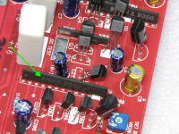
These are in, I thought they were just resistor nw?
An externally hosted image should be here but it was not working when we last tested it.
Earlier, I stated that ANW6 was the most problematic. It's was actually ANW7.
The modules varied but the attached diagram shows what the ANW7 was. The 39 ohm resistors appeared to be changed to 120 (or vice-versa). OThe modules had diodes as well as resistors. The biggest problem with the ANW7 was that the 8.2k resistors on the ends began to have leakage to other components and that caused various problems.
The modules varied but the attached diagram shows what the ANW7 was. The 39 ohm resistors appeared to be changed to 120 (or vice-versa). OThe modules had diodes as well as resistors. The biggest problem with the ANW7 was that the 8.2k resistors on the ends began to have leakage to other components and that caused various problems.
Attachments
I measured the black modules, VARNW 9249 written on it. They seems to be diodes. All 4 measure the same about 0,7V with DMM (1 pair / channel).
Connected a resistive load 4 ohm, 1kHz signal generator -> normal output sinewave both channels....sighhh....
Transistors are not clamped to the heatsink, so just short testing are possible.
Connected a resistive load 4 ohm, 1kHz signal generator -> normal output sinewave both channels....sighhh....
Transistors are not clamped to the heatsink, so just short testing are possible.
The isolator is the kapton foil and is OK, I had the protection also without clamping to the heatsink. There is a ANW5 near the opamps and gainstage, known problems with these?
The amp is working ok now, have to check for bad solderings..
The amp is working ok now, have to check for bad solderings..
I don't remember having a problem with the ANW5 but it's been about 20 years since these were regularly coming in for repair the memory is a bit hazy.
- Status
- Not open for further replies.
- Home
- General Interest
- Car Audio
- Hifonics Colossus VIII repair