This Standard PSU has been buried over in the HPA-1 headphone amplifier thread, so I've pulled it out and given it its own one.
Its intended for preamplifier/small signal and headphone amplifier applications:-
Here's a link to the PSU page that has the full build doc including noise measurements and BOM. You can also get a PCB for the PSU as well
Hifisonix Standard PSU
I'll be happy to answer any questions.
🙂
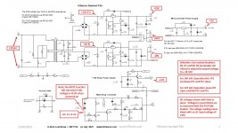
Its intended for preamplifier/small signal and headphone amplifier applications:-
- Compact - 170mm x 75mm X 50mm (L x W x H)
- Johnson noise (aka thermal noise) and mains hum < 100 uV 20Hz – 20 kHz at full load (see measurements in the document on the website)
- Uses low noise Nuvotem Talema PCB Mount transformer (15VA or 25VA)
- 120 or 240 VAC operation
- +-18V DC output
- 25VA or 15 VA versions
- +-400mA per rail (25VA version) or +- 300mA per rail (15VA version)
- Incorporates MUTE relay driver function
- Includes a +12V at 40mA relay power supply
- Built in +5 or +3.3V regulator output at 60mA to power auxiliary micro controller
- Ground lifter function +-0.7V with optional bypass using offboard toggle switch
- Rectifier snubbers included
- Input/output connections via 6.3mm push on TAB connectors (accept Earth/safety ground wire – soldered)
Here's a link to the PSU page that has the full build doc including noise measurements and BOM. You can also get a PCB for the PSU as well
Hifisonix Standard PSU
I'll be happy to answer any questions.
🙂
Attachments
Last edited:
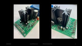
I have almost 100% of the components installed. I'm pausing for a bit to set up my scope and Cheapomodo to measure an AMGIS toroid as well as the Talema. Afterwards, I will post the values that reduce the ringing the best. 🙂
Andrew took a break for what was supposed to be a quick project but ended up not.
I am having difficulties getting 18V out of the power supply and my mute relay is not activating. I have verified soldering, components, and orientation. I changed R7-8 R8-9 from 120to 270 and increased 16V to 17V on the output and was going to go higher however you stated there was something wrong I should not have to do that. Here are the voltage reading I get now with the 270 ohm values.
I am having difficulties getting 18V out of the power supply and my mute relay is not activating. I have verified soldering, components, and orientation. I changed R7-8 R8-9 from 120to 270 and increased 16V to 17V on the output and was going to go higher however you stated there was something wrong I should not have to do that. Here are the voltage reading I get now with the 270 ohm values.
Attachments
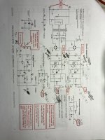
Hi Wirewiggler - sorry you have problems. The raw DC voltages on the inputs to the regulator section look good as does the +5V output and relay supply
You should only have one of the 270 Ohm resistors installed in the R8/R9 position and one in the R6/R7 position. You may find with one installed, the output voltage is a bit above 18V - you can always then trim it back a bit with a 1-2.7k resistor in parallel but for most opamp applications +-18.5 will be fine.
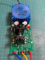
I've just checked mine on the bench and its +-18.34 with just one 270 Ohm in position - picture below.
I'll add some additional notes to the build doc to make this point clearer.
You should only have one of the 270 Ohm resistors installed in the R8/R9 position and one in the R6/R7 position. You may find with one installed, the output voltage is a bit above 18V - you can always then trim it back a bit with a 1-2.7k resistor in parallel but for most opamp applications +-18.5 will be fine.
I've just checked mine on the bench and its +-18.34 with just one 270 Ohm in position - picture below.
I'll add some additional notes to the build doc to make this point clearer.
Attachments
Last edited:
Well I removed one 270 resistor and that brought it up to 17.8 V . I can live with that, everything else is good so I will case it up. Will post picture of completed amp.
thanks
Bill
thanks
Bill
That will work well.
Unfortunately the ref voltage tolerance on the LM317 is quite high when you are asking it to provide 18V outputs as is the case here. To get it to 18V, you can replace the 270 Ohms with a 330 Ohm.
Unfortunately the ref voltage tolerance on the LM317 is quite high when you are asking it to provide 18V outputs as is the case here. To get it to 18V, you can replace the 270 Ohms with a 330 Ohm.
- Home
- Amplifiers
- Power Supplies
- Hifisonix Standard PSU