The usual scheme to use cheap power Xfmrs for an OT generally runs into the limitation of primary impedance attainable and AC voltage swing at LF.
One can use two P-P Xfmrs in the Norman Crowhurst Twin Coupled mode to double the primary Z and V, but then one is stuck with 50% CFB. And no further Z increase is obtainable.
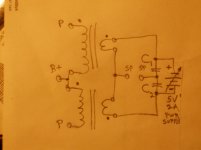
Here is a method, using the simplest single winding primary Xfmrs, with no need to use CFB, although that can still be done if wanted.
More Xfmrs can be connected in series in each phase side to get even higher primary Z. They need to all be the same turns ratio in order for secondary DC current to neutralize the primary DC currents accurately. Secondary DC is kept out of the speaker, and the AC signal is kept out of the LV power supply.
One converts the primary DC current to the higher secondary current using the turns ratio, then use a LV power supply to neutralize that current. Secondary current will be the LV divided by the total secondary copper resistance it flows thru.
Power consumption is only a few Watts. (a current source type compensation would require high Watts)
Warning!!
Increasing the voltage rating this way may lead to exceeding the V ratings of the individual Xfmrs. (primary to secondary and primary to core AC and DC ratings)
NOT recommended under any circumstances for HV transmitting tubes.
Connecting secondaries in parallel (per phase side) is NOT recommended, since a small difference in copper resistance would lead to unequal compensation currents in the paralleled secondary Xfmrs. Unequal copper resistance between two similar Xfmrs could be compensated by DC biasing the tubes slightly differently.
Keep in mind that normal P-P operation reaches 2X the B+ under ideal conditions. Resonances (Xfmr or speaker ) and loose connections can lead to 10X easily. Then there are corona and insulation leakage issues at HV.
One can use two P-P Xfmrs in the Norman Crowhurst Twin Coupled mode to double the primary Z and V, but then one is stuck with 50% CFB. And no further Z increase is obtainable.
Here is a method, using the simplest single winding primary Xfmrs, with no need to use CFB, although that can still be done if wanted.
More Xfmrs can be connected in series in each phase side to get even higher primary Z. They need to all be the same turns ratio in order for secondary DC current to neutralize the primary DC currents accurately. Secondary DC is kept out of the speaker, and the AC signal is kept out of the LV power supply.
One converts the primary DC current to the higher secondary current using the turns ratio, then use a LV power supply to neutralize that current. Secondary current will be the LV divided by the total secondary copper resistance it flows thru.
Power consumption is only a few Watts. (a current source type compensation would require high Watts)
Warning!!
Increasing the voltage rating this way may lead to exceeding the V ratings of the individual Xfmrs. (primary to secondary and primary to core AC and DC ratings)
NOT recommended under any circumstances for HV transmitting tubes.
Connecting secondaries in parallel (per phase side) is NOT recommended, since a small difference in copper resistance would lead to unequal compensation currents in the paralleled secondary Xfmrs. Unequal copper resistance between two similar Xfmrs could be compensated by DC biasing the tubes slightly differently.
Keep in mind that normal P-P operation reaches 2X the B+ under ideal conditions. Resonances (Xfmr or speaker ) and loose connections can lead to 10X easily. Then there are corona and insulation leakage issues at HV.
Attachments
Last edited:
Measurement of turns ratio may include some inherent error from the magnetising current in to the driven winding.
Have you tried any tests to confirm neutralisation, or has it just been turns ratio so far?
Have you settled on any advise for C1 and C2 selection? It seems like they could be standard e-caps.
I can see the HV transient warning for a primary, as the other primary is not magnetically coupled, and so entering/exiting cut-off as in class AB could induce an inductive transient on each primary that may only be poorly coupled to its secondary. It may well be worth including over-voltage protection on each primary winding, such as an RC or a MOV, as the often seen flyback diode is not able to catch 2x B+ spikes in this situation, and the leakage inductance of the primary could be considerably more than seen in normal OPTs.
Last edited:
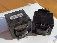
I haven't done any testing as of yet. I have a big box of Signal Transformer DPC-16-1500 Xfmrs that I got cheap (no pin #s marked on them). These are 120V/120V - 8V/8V. 1500V isolation, 24 Watt. Got them and several other voltage output models a few years ago when they were cheap. (not so cheap on EBAY now) Collecting dust, hence some creative thinking.
Several means of testing them come to mind. One could drive them P-P in class A and look for how constant the B+ current is versus the neutralization current.
Or one could put the same neutralizer circuit on both primary and secondary sides and just drive one side with a signal generator, observing the other side on a scope for flat-topping versus DC current match.
Another way would be to check primary inductance versus DC current (equiv.) matching between primary and secondary.
The C1 and C2 caps have to carry the AC signal current, so need to be big. (the LV power supply likely will already have a big cap on its output)
They can be eliminated however, by using four xfmrs (or secondaries) with two secondaries replacing the C1 and C2 caps. A bridge circuit then. (with the dual secondary DPC xfmrs, one can get away with just two xfmrs and no caps using the bridge form, on primary or secondary sides for DC testing)
With the secondaries effectively coupled together, one may approach interleaving effects, maybe. (leakage Ls effectively in parallel, but distributed capacitance in parallel too) Will have to frequency test the scheme. RC snubbers on the primaries would probably be a good idea though.
One could also add a little AC HF bias this way to mimic the HF bias of the magnetics on a tape recorder. (removing hysteresis and maybe magnetizing current too?)
CFB can be done easily by using one xfmr primary winding set for the cathode windings and one or more xfmr primary winding sets for the plate windings.
Attachments
Last edited:
If you drove the primary in class A, then the secondary side output signal should have a minimum distortion level - the distortion should increase for secondary current either side of a core flux null.
Those 110-110, 8-8V transformers seem excellent for normal PP OPT use !?
Those 110-110, 8-8V transformers seem excellent for normal PP OPT use !?
Do I understand you correctly that the plan is to use ungapped transformers with standing DC current in the primaries, at least partially balanced with a roughly equal ampere-turns of DC in the secondary?
Folks will sometimes suggest something like this using a shunt current source, but it always fails because of power requirements (equal to the actual amplifier, plus overhead). Your plan of a series current source is elegant and AFAIK new.
One potential issue is the nonlinearity of iron cores near zero crossing (B/H slope flattens) but this is also true in a well balanced push-pull output transformer to some extent.
All good fortune,
Chris
If you drove the primary in class A, then the secondary side output signal should have a minimum distortion level - the distortion should increase for secondary current either side of a core flux null.
Yes, that's another good test means.
Do I understand you correctly that the plan is to use ungapped transformers with standing DC current in the primaries, at least partially balanced with a roughly equal ampere-turns of DC in the secondary?
Yes, no gaps. DC flux cancelled at idle most likely. The one problem I see is 2nd Harmonic distortion in the output tubes will cause standing DC current to increase at higher signal amplitude. This could be minimized by using local N Fdbks to linearize the tubes.
Or, for class A, the B+ current could be monitored to adjust the DC neutralization. ( LP freq. filtered, this fixes class A and AB, see below) This B+ current monitor signal could just be added to the LV power supply V reference, after some appropriate attenuation.
For class AB, maybe one could subtract a rectified signal component from the B+ current monitor. Adjustment level would depend on how much class B is set up by the biasing, and would need some threshold subtraction from it for the class A part.
An easier way would seem to be just limiting the B+ current monitoring to below the signal frequency. Envelope following, but not AC signal following. Works for class A or class AB. A simple fix.
Non-linear magnetizing current versus signal level is another potential problem. I think that would be symmetrical at any fixed signal level though, so would end up nulling out (over an AC signal cycle) in the B+ current monitor. So a 20 Hz, or lower, low pass filter should be quite useful in the B+ current monitor. (so only signal envelope is followed, not instantaneous signal)
So looks like just a LP filter in the B+ current monitor fixes the DC compensation correction amount. If combined with local N Fdbks for the output tubes, not much to do even.
One needs to prevent any DC drive signal coming into the output tubes.
The compensation would be correcting both Xfmrs, when only one xfmr would need it.
Seems do-able. But not quite as simple as one would like.
Last edited:
One does need the (LP filtered) B+ current monitoring compensation, to the DC neutralization, for class AB, even with local N Fdbk tube linearization. Since the class B part looks just like 2nd Harmonic increase of primary current (for each xfmr).
Last edited:
Secondary current will be the LV divided by the total secondary copper resistance it flows thru.
I think that's the problem. Most stepdown power transformers have low secondary DCR. Same goes for audio OPT. Have you measured the secondary DCR, under 1R, on any PT's to see if you might short the LV PS itself and burn it up. It's series connected through the windings. So you might have to add resistors, too, to reduce the load on it. Anyway, how much $$ would anyone save by using 2 PT's and a LV PT and coupling caps, resistors, and have to wonder if it is all HI-FI, without jumping through other FB additions for FR improvements? Saving money is the original objective, right? How much is complexity and hassle worth?
Last edited:
The DPC-16-1500 Xfmr measures 0.6 Ohm and 0.7 Ohm on the 8V secondaries. (meter lead R compensated) The primaries measure 71 Ohm and 78 Ohm.
4 Xfmrs (24 Watt each at 60 Hz, series/parallel in the bridge config.) would allow 30 Watts at 20 Hz. Using some 6L6GC in P-P class A, they would be idling around 70 mA each. With 110V/110V to 8V/8V we can rig windings for 220V to 8V giving 6050 Ohm to 8 Ohm, approx, ( 8V windings would be more like 9.5V to account for 1.5V drop at full load of 1.5 A on each to get 8V out)
So 4290 Ohm primary to 8 Ohm secondary actual. 70 mA idle current would translate to 23 x .07 = 1.62 Amp equiv. at secondary. Then 1.62 x 0.65 Ohm (sec in parallel) would lead to 1 V IR drop for DC. (the full P to P Zprimary used in calcs accounts for the -two- 70 mA idle tubes I think)
Then for the bridge configuration we have 2 secondaries in series in each side, and 2 sides in parallel. So 2V drop at 3.24 Amps for the DC power supply. Not unreasonable if you use a 2V power supply. 6.5 Watts for DC.
One might want to use 6X Xfmrs to get the primary Z up to 6435 Ohms. (and 45 Watt audio rating) Then the DC supply would be 3V at 3.24 Amps. 10 Watts for DC.
The E-I lamnation internal gaps might handle the 2nd harmonic increase in DC at full power alone. But local N Fdbks may be needed anyway to drop the output Z.
The 2X 6L6GC giving 23500 Ohm /2 Rp reduced by the OT to 22 Ohms Ri for 4X Xfmrs or 14.6 Ohms Ri for 6X Xfmrs. Some local N Fdbks would be welcome to drop the output Z down another 5X to 10X, reducing 2nd harmonic DC by a similar amount.
So it seems practical for class A. Cost me $3 or $4 each in quantity for the Xfmrs as I recall. (like 10 years ago) It does require rather more wiring up, but these are PC mount. (NOT so practical however with EBAY pricing on them currently, $7.80 to $15.50 each, but maybe a quantity deal can be found, there are lots of other surplus types out there.)
Class AB adds some cathode current monitoring (some low value cathode resistors, with higher value averaging resistors to sum) to vary the LV power supply reference V. Class AB would only need to neutralize around 1/2 the DC idle current of class A, on average.
Note:
The double primary and double secondary configuration of the DPC Xfmrs allows one to interleave the primary sections into each tube current path, as some have been doing with toroid power xfmrs lately. So that balanced DC operation can be obtained in the conventional way on the primary side. This does lead to higher distributed capacitance typically, when more Xfmrs are used in series. (dual primaries usually don't have great insulation between them, and can even be wound bifilar. )
The Signal Corp DPC-16-1500 Xfmrs I have measure 265 pF common mode between the two primaries. And 220 pF common mode between dual primary to dual secondary. Some EWC DPC-40-600 Xfmrs I have have higher primary to primary capacitance, 379 pF. (and 330 pF primary to secondary)
Last edited:
I just checked an Avel-Lindberg toroidal power transformer for capacitance comparison. This is a 130 VA rated dual 115V primary to dual 35V secondary. (47 Hz to 400 Hz rated)
Primary to primary is 20.8 nF (20800 pF)
CM Primaries to CM secondaries is 860 pF
Not an Xfmr I would use for series connected primaries for audio.
(High primary to primary capacitance is actually advantageous for 230V power use, since the capacitance helps cancel out the primary inductance for power factor improvement.)
In oz there are many 50W Qu Hal 240:12Vac transformers being replaced (and thrown out). Only a low % of those came with a dual primary (120+120) and they have been easily used in typical PP OPT duty quite well. As I see it, it's the high % of transformers with a single 240Vac primary that would be a target for this type of neutralising concept.
One convenient option may be to use a 5V or 12V to lower Vdc smps module to act as the secondary side DC supply. There are quite a few cheap ebay modules that could suit - and some may have a variable output voltage to allow a current level to be set (although that would depend on DCR of the windings which would vary a bit with self-heating). The setup of the secondary circuit alleviates any impact of high frequency ripple from such a smps module.
I'd suggest that as this type of application has inherent distortion generating mechanisms then it may be more applicable to the guitar amp diyers (who actually want 2nd harmonic added). There is certainly a small following of guitar amp diyers who enjoy repurposing cheap throwaway parts, and many already use discarded 50W 12Vac lighting PT's for powering their amps (both for heater supply and using double-doublers or back-to-back for B+ generation).
Last edited:
With the AC cancelled out of the neutralization secondary feed points, one could use a LV current source instead, which would fit switch mode IC converters well. That would not be affected by winding resistance then. At least for a class A Amp. Class AB still has variation of DC with signal level in each primary side (and xfmr), which would still need some B+ current monitoring to adjust the neutralization current.
For class AB it may be simpler to just use Circlotron mode, which self cancels the DC and allows multiple single primary xfmrs to be used. One can use some driver stage plate load bootstrapping if 50% FB is not wanted. Partial bootstrapping would allow lower levels of CFB, like 25%, as well.
I have a box load of Signal DPC 120-200 120V/120V 100V/100V 24 Watt xfmrs also, just for this purpose as the floating power supplies. They also measure in the 200 pF capacitance range between windings.
Split bobbin OEM xfmrs can do even better for low pF. A 175VA type measures at 86 pF, and a 43 VA model measures at 50 pF (primaries to secondaries).
A simple capacitance measurement between primary and secondary windings may not be a reasonable indicator of anything, and may only be of interest if global feedback is being applied.
If there was incentive to use PT's as OPT's for a hi-fi application with GNF, then it could be worth measuring the impedance and frequency response of the PT for different primary configurations (eg. which winding end is effectively grounded), as the impedance plot may give a better indicator of shunt capacitance and leakage inductance for different configurations.
If there was incentive to use PT's as OPT's for a hi-fi application with GNF, then it could be worth measuring the impedance and frequency response of the PT for different primary configurations (eg. which winding end is effectively grounded), as the impedance plot may give a better indicator of shunt capacitance and leakage inductance for different configurations.
For the xfmrs being used as an OT, one would like to know the primary inductance and the primary resonance freq. and leakage L to the secondary. Also the max voltage at LF.
For the Circlotron floating power xfmrs, the primary to secondary capacitance is driven at audio freq. directly, so is important. I wouldn't want the earlier toroid with 20800 pF.
These can all be measured with a signal gen. and scope and an LC meter.
And as you mentioned, very helpful to know how the windings are ordered on the core for best series connections. Interwinding capacitances can help determine that.
A major issue I would want to know is whether the windings are layered or random wound. Inter-winding capacitances can help there to know if the primaries are semi-bifilar wound. I would guess that progressive wound toroids are fairly rare, at least for power use. The winding machines are considerably more expensive to do progressive winds.
All these measurements and analysis makes one wonder if it is all worth it to save a few $$ using power xfmrs versus audio ones. But one should do the same for the audio ones to check if they are competently made. At least once to instill confidence.
By the way, I just got in some Edcor 60 Watt 3.3K to multiple secondary OTs, for those TV Sweep tube enthusiasts out there. Should be on Edcor's standard product list soon, after they finish a revamp of their website in progress. I wanted something available for the smaller to mid size Sweep tubes, like 6DQ5, 6HJ5, 12GE5, 12JN6, 21HB5, 17KV6, 12GT5, 17JT6, 22JR6, 22JG6, 21LG6, 6EX6, 6CD6..... The bigger Sweeps already have a 100 Watt 3.3K and 2.5K OT available. There is a 60 Watt 4.2K OT there already too.
Last edited:
The 6DQ5 tube actually belongs to the "big" tubes according to the output power criteria, because I got 100W of output power with it in a practically realized amplifier. This amplifier has been operating for years without failure and the need for frequent changes of output tubes (which speaks in favor of not being overloaded in real amplifier operation) with Ua ~ 600V, Ug2 = 150V (stable), -Ug1 ~ 45V, Ia ~ 2x30mA (without signal) with primary transformer output impedance Raa ~ 3800 Ohms. In practice it is a 200W amplifier with 4 pieces of 6DQ5 and an output transformer of Raa ~ 1900 Ohms, and the excitation on G1 is without lattice current (Class AB1) with Ug1 ~ 2x40Veff.
In the beginning, I started this amplifier with 6HF5 tubes, but they are relatively difficult to find at reasonable prices, so I replaced them with 6DQ5.
In practice, I did not notice any differences between these tubes in this amplifier, although the manufacturers state that for 6HF5 the anode and G2 dissipation is higher (Pa = 28W, Pg2 = 5.5W) than the 6DQ5 tube (Pa = 24W, Pg2 = 3.2W).
Last edited:
I guess the 24+ Watt rated tubes like 6DQ5, 6HJ5, 17KV6, 21LG6, 6CB5 ....
can do over the 60 Watt level for P-P without much trouble. (600V B+ helps the efficiency!) All depends on how conservatively they are run. I think George gets some hefty Watts out of those dingbat cheap 15 Watt 6DN6s (later ones rated 20 Watt apparently) and unreasonable Watts with little 6GF5s too (hopefully with some cooling fan).
By the way, I've seen a few of those "odd" winged 6DQ5s go by on Ebay in the last 1/2 year. I asked at Vacuumtubes.net if they had any, but they said they hadn't seen any.
18 Watt sweeps are probably fitting the 60 Watt P-P OT better. There was an obvious hole in Edcor's OT lineup for 60 Watt before without the 3.3K model. Although 4.2K was there for the 18 Watters. Another hole remains at 5K 60 Watt.
Last edited:
They had the 26DQ5 at.vacuumtubes.net earlier this year. Bought my spare set for this and a couple more to play with. He said he still had some left.
6 volt are always more expensive, so I didn’t inquire. Custom trafos give one the opportunity to use whatever heater you can get.
6 volt are always more expensive, so I didn’t inquire. Custom trafos give one the opportunity to use whatever heater you can get.
Attachments
- Home
- Amplifiers
- Tubes / Valves
- Hi Z P-P OTs using multiple simple Xfmrs