Hello, I'd like to undertake the construction of my third diy amplifier.
Can someone provides me schematics of a truly hi-fi (really wide frequency response, lowest possible distortion (minimum 1%) at high wattage, minimum 10W output, 6L6 triode tube for output stage in SE or PP and triode (6SL7, 6SN7 ecc.) tubes for preampfification stage?
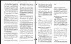
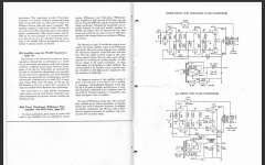
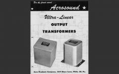
I have found an old schematic from the Acrosound company but the amplifier seems a modification of the one ("Triode circuit with Acrosound T250 transformer) offered in its catalogue (see page 7 in the catalogue) - any thoughts about the two schematics would be very appreciated).
Moreover I was wondering if one should use a phono preamplifier are two preampfification stages in the power amplifier redundant? (so another requirement would be a single preampfification stage like the schematic "6L6 circuit with TO280 transformer" always at page 7").
Can someone provides me schematics of a truly hi-fi (really wide frequency response, lowest possible distortion (minimum 1%) at high wattage, minimum 10W output, 6L6 triode tube for output stage in SE or PP and triode (6SL7, 6SN7 ecc.) tubes for preampfification stage?
I have found an old schematic from the Acrosound company but the amplifier seems a modification of the one ("Triode circuit with Acrosound T250 transformer) offered in its catalogue (see page 7 in the catalogue) - any thoughts about the two schematics would be very appreciated).
Moreover I was wondering if one should use a phono preamplifier are two preampfification stages in the power amplifier redundant? (so another requirement would be a single preampfification stage like the schematic "6L6 circuit with TO280 transformer" always at page 7").
Attachments
I really don't like that phase splitter style...
Easy design and simple build if going triode output stage. 6SL7 concertina feeding 6L6 should work fine, although the 12AT7 will have an easier time driving the output grids. No need for three stages if going triode with a strong enough driver.
Do you already have power and output transformers on hand? Any preference as to brand? What's the highest voltage you want to play with? 350-400 volts would be a good range for a nice cathode biased build, since you will be dropping a bit through the power supply bits. Do you want all tube, or is solid state rectification allowed?
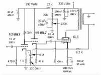
Something like this with some component changes to suit your power iron choice, and output tubes would be a nice simple build-
An externally hosted image should be here but it was not working when we last tested it.
How about triode strapping a Heathkit W5M? It uses the 9 pin versions of the tubes you mention.
Do you want 10W @ 1% THD without feedback, or is feedback permissible?
Do you want 10W @ 1% THD without feedback, or is feedback permissible?
Good points. No preference about the brand of power and transformer (or maybe Hammond?), 300 to 350V, all tube (no solid state rectification and have a preference for the 5Y3).I really don't like that phase splitter style... <snip>
Something like this with some component changes to suit your power iron choice, and output tubes would be a nice simple build- <snip>
Interesting schematic, what about the frequency response, power output and distortion? No 12V pentode tubes (thats because have stock of 6SL7, 6SQ7, 6J5 etc).
How about triode strapping a Heathkit W5M? It uses the 9 pin versions of the tubes you mention.
Do you want 10W @ 1% THD without feedback, or is feedback permissible?
The Heathkit W5M seems overpowered to me (25W). And as said prefer use octal 6SL7, 6QS7 (got spare parts).
Feedback is permissible but Id like to keep the distortion 1% or less.
Moreover should I consider three or two stage if I want add a phono preamplifier?
Alright, looking at some old notes of mine, I found the layout for my last 6L6GC build. I'll lash up a schematic soon, but here is a quick description, and operating points/values...
GE 6L6GC, late sixties production (more rugged than current production)
JAN Sylvania 6SL7GT (very nice, very consistent)
GE 6SN7GTA (common variety you see everywhere)
275-0-275 power transformer (console pull of unknown manufacture)
6000K:8 center tapped output transformers ( also console pulls, several pounds each, unknown manufacture)
6SL7 voltage amplifier, 220k plate resistor, 2200r cathode resistor with 33k feedback resistor to output winding of transformer
Output from 6SL7 plate direct coupled to grid of 6SN7 concertina, 22k plate/cathode resistors
Output tubes set up triode connected (via 100R screen resistors) with 270k grid leak resistors, 330nF polystyrene coupling caps, a shared 390R cathode resistor, bypassed with 1000uF electrolytic and a 4uF film, later changed to individual 220R resistors with individual bypassing of same cap values (to better utilise mismatched bulk tubes, such as Russian 6P3S) which all worked very well. Cathode voltage (bias voltage) ended up around 20~25 volts with most tubes.
I used solid state rectification via 1N4007 diodes (with series resistors to mimic tube rectification), and a CRCRCRC filter for the input/splitter stage, output stage fed right off the first reservoir cap. AC heaters. Zero hum. Overall B+ at the output tubes around 360 volts, input stage around 320 volts.
Power output around 8 watts just before clipping. It sounded fantastic 🙂
Doing this all over again, I would use the splitter bias arrangement that I used in my 6SN7 flea amplifier, so that the split load stage has more headroom, and maybe run a higher overall supply voltage (400?) But otherwise I think it was a good overall build.
As far as the phono preamp, will you want to put that in the same case, or separate? For what its worth, unlike to keep phono stages in separate chassis so they are easier to keep noise free, and its more versatile too.
Also regarding the 5Y3, I think one per channel would work (or parallel connected) but I wouldn't try to do a stereo build with a single one. They are also fairly limited in how much capacitance they can handle, so choke input makes more sense with them, adding expense. I'm a solid state guy for my rectification, so I can't comment too much further there.
Thank you so much for the reply. I'm intended to built a mono unit so no problem referring to the 5Y3 issue.
Regarding the Phono preampfification stage I'd like to try to build it in the same chassis (not binding), also no problem if I have to use a filter choke.
Would you be so kind to provide me the model of the amp you are suggesting so I can try to search more information about it (i.e. frequency response, distortion, if it is in PP or SE configuration, etc.)?
Last edited:
Well, its sort of a generic push pull design, as old as tubes themselves. As far as distortion, it should be well under 1% at average listening levels. Frequency response is consistently flat through the audio band.
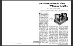
Looking at specific names, a Williamson type or Mullard 5-20 might fit your needs, but since they are iconic and generic amps, there are thousands of variations on them. It's easy enough to swap out different output tubes for the most part, so long as the relevant supporting circuitry is modified to suit, and the front end is up to par.
Looking at specific names, a Williamson type or Mullard 5-20 might fit your needs, but since they are iconic and generic amps, there are thousands of variations on them. It's easy enough to swap out different output tubes for the most part, so long as the relevant supporting circuitry is modified to suit, and the front end is up to par.
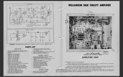
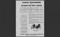
Very interesting suggestion to look at the Williamson or Mullard 5-20 typology! Found some very interesting schematics especially of the Williamson (all triode). What do you think? Probably I should avoid the ones with the cut of 50k in the frequency response.
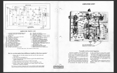
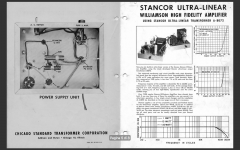
What modifications need to be done in order to use 6L6 with the "Stancor ultra linear" schematic on page 7?
Moreover why there are two jacks between the power output tubes?
What modifications need to be done in order to use 6L6 with the "Stancor ultra linear" schematic on page 7?
Moreover why there are two jacks between the power output tubes?
Attachments
-
 105_williamson_3.png794.1 KB · Views: 236
 -
 105_williamson_2.png609.7 KB · Views: 185
 -
 105_williamson_1.png273.5 KB · Views: 151
 -
 stancor_5.png425.2 KB · Views: 230
 -
 stancor_4.png775.1 KB · Views: 236
 -
 stancor_3.png796.6 KB · Views: 234
 -
 stancor_2.png857.1 KB · Views: 528
 -
 stancor_1.png467.3 KB · Views: 391
Last edited:
here's some:
(google translate may help)
This site has two 6L6 SE with 6SL7, a 6L6 PP with 12AT7 & 12AU7 schematics, chassis layouts, wiring, etc.
furo-visu Index
6L6 Triode SE
6L6GC SE
6L6 PP
(google translate may help)
This site has two 6L6 SE with 6SL7, a 6L6 PP with 12AT7 & 12AU7 schematics, chassis layouts, wiring, etc.
furo-visu Index
6L6 Triode SE
6L6GC SE
6L6 PP
Last edited:
I agree with Lingwendil (post #2):
This is why I do not like "serial phase splitting" (or whatever it is named).
The second grid (bottom grid in the schematic) of the 6SL7 is driven by 470k and 560k in parallel.
I estimate the gain of the 6SL7 triodes at about 35.
The plate to grid capacitance is about 1.5pF, and with the miller effect, about 50pF.
The 470k and 560k resistors and the 75 pf has a -3dB bandwidth of about 12 kHz (on the second 6SL7 grid).
That means for frequencies at and above 12kHz, the amp is effectively Single Ended.
Negative feedback does not fix that. The lower grid is always driven by -3 dB at 12kHz (and worse as frequencies go above that).
Hi HMV130,
If you still want to make SE amp I would consider this circuit from Alex Kitic - RH Universal as it is already being built by others with good results.
Original site from designer: RH Amplifiers: RH Universal v.2 – Totally Universal
One example from other forum: Tube DIY Asylum
I made myself RH84 with EL84 in SE and it was the best sound I ever heard from this small tube in SE configuration.
Thanks for the suggestion. One of them seems interesting tho can't find any reference about the distortion.here's some:
(google translate may help)
Thank you so much for the explanation. So which schematic you suggest? The second proposed by Lingwendil (6L6GCPP and 6SL7)?I agree with Lingwendil (post #2):
This is why I do not like "serial phase splitting" (or whatever it is named).
Thanks for the suggestion. A 6V6 SE RH807 has been my first diy amp 🙂. I'm still using it with satisfaction but want to upgrade my sound system both in frequency response/distortion and power output.I made myself RH84 with EL84 in SE and it was the best sound I ever heard from this small tube in SE configuration.
Please consider the attached file. Is this a more powerful and better performer 6L6 tube amp based on the RH?
I would like to see the schematic of this too. Would you be so kind to upload it? 🙂 Thank you in advice. Do you know precisely the frequency range in which the response is flat?Alright, looking at some old notes of mine, I found the layout for my last 6L6GC build.
Attachments
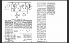
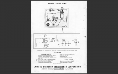
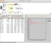
I also managed to find the article about the first schematic I posted in this topic. I just tested the PSU and the B+ produced (955V) does not match the B+ indicated (385V). Am I missing something? 😕
Full article here.
Full article here.
Attachments
PSUDII wants the voltage from each HV phase to center tap, you input 740 which would be the end to end voltage, not end to center tap. Halve that to 370v (like in the schematic) and you should be fine.
I also do not prefer the concertina phase splitter either (the splitter that uses matched resistors in the plate and cathode). It is the possible filament to cathode leakage; the filament to cathode capacitance; and the requirement to use a raised filament voltage that I see as possible problems.
I like the input stage with a cathode coupled phase splitter the best (a current source and cathodes connected together). But like all the other phase splitters, there are tradeoffs. You need a Negative power supply to power the constant current source.
I have an idea on how to use the filament supply with rectifier and filter to supply this negative voltage, while still supplying AC to the filaments (but have not tested that method, so may stick to using a separate negative supply).
Another method I use to get push pull is to do the phase splitting in the output stage, the OddWatt amps are one example.
But unlike the OddWatt amps, I do not use the SRPP as in those amps, and I do not use Ultra Linear as in those amps, and I do not use Negative Feedback as in those amps.
Instead I use a single Triode with a plate current source for the input stage, A high voltage NPN transistor for the output tubes common cathode current source, and Triode wired Pentodes or Triode wired Beam Power output tubes. This trades off power for other desirable aspects of the amp.
Well, we all have our preferences.
Last edited:
I like differential amplifiers only when I already have a negative rail to use, and like that you get full stage gain rather than stage gain/2 in the concertina, and in most of my past testing it was much easier to get lower distortion overall (especially odd harmonics) with the concertina... However, the differential really makes itself a contender when you incorporate individual cathode degeneration, and drive each grid from a balanced/differential signal... less gain, more complexity, but very nice almost SE arrangement of overall low THD, and excellent AC as well as DC balance. If cascading stages or running a balanced input, or an input transformer, things get really interesting.
Want to have some real fun? My damn-the-torpedoes, bring-out-the-big-guns way of swinging lots of voltage is to run a CCS loaded concertina into a mosfet split-load splitter, followed by a differential standing on a CCS with individual cathode resistors, with source followers. Choose your voltages and tubes right, and swinging 200 volts or more at each output grid for sweep tubes or screen drive is childs play, with very low overall distortion bettering most differential stages. Think the 6L6GC AB2 thread idea, with a concertina replacing the first differential... But, that's a discussion for another time 🙂
Want to have some real fun? My damn-the-torpedoes, bring-out-the-big-guns way of swinging lots of voltage is to run a CCS loaded concertina into a mosfet split-load splitter, followed by a differential standing on a CCS with individual cathode resistors, with source followers. Choose your voltages and tubes right, and swinging 200 volts or more at each output grid for sweep tubes or screen drive is childs play, with very low overall distortion bettering most differential stages. Think the 6L6GC AB2 thread idea, with a concertina replacing the first differential... But, that's a discussion for another time 🙂
The W5M isn't going to make anywhere near 20W with the outputs triode strapped. You will get nice Peerless output transformers though and you can always convert to 6B4G or 300B.
I second the W5M, it's a great design in my opinion. There are two compensation networks that depending on the output transformer you will need to dial in with an oscilloscope. I recently modified a W5M to use 6BG6GA's and they look boss. The performance stayed the same and the tubes are cheap for good NOS RCA compared to KT66 or 6L6GC's.
I did this with a pair of push-pull amps I made a long time ago with 6LU8s. I rectified the 6.3V heater winding and made a -8V DC supply out of it, then used a cascoded BJT current source for the differential pair. It worked quite nicely!I have an idea on how to use the filament supply with rectifier and filter to supply this negative voltage, while still supplying AC to the filaments (but have not tested that method, so may stick to using a separate negative supply).
- Status
- Not open for further replies.
- Home
- Amplifiers
- Tubes / Valves
- Hi-fi 6L6 SE or PP with triode preamp stages