since BJTs can be configured as diodes by tying their base to collector, I was wondering if the same can be done with MOSFET, specifically IRF540.
initial simulation seems very promising as the "diode" has extremely sharp cut off.
Has anyone tried this in real life? How is such a set-up different from a Hexfred?
initial simulation seems very promising as the "diode" has extremely sharp cut off.
Has anyone tried this in real life? How is such a set-up different from a Hexfred?
Hi Millwood,
Have a look at http://www.ne.jp/asahi/evo/amp/active_rectifier/report.htm , where Shinichi Kamijo shows just that (already 5 years old). I have not studied this article in detail (I'm also lacking knowledge of Japanese).
Nowadays in computer systems with low voltage/high currents circuits this is also common practice to reduce power losses. Search for 'synchronous rectification', e.g. http://www.maxim-ic.com/appnotes.cfm/appnote_number/652/ln/en but this is mainly (only?) related to SMPS circuits.
Steven
Unless you aren't after synchronous rectification, you can use the intrinsic diode but this has more voltage drop than a regular one.
Between source (=Anode of the diode) and drain you allways has a diode.
Conclusion: Not a very good idea.
Between source (=Anode of the diode) and drain you allways has a diode.
Conclusion: Not a very good idea.
Steven said:Have a look at http://www.ne.jp/asahi/evo/amp/active_rectifier/report.htm , where Shinichi Kamijo shows just that (already 5 years old).
Steven
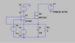
Steven: thanks for the link. Here is a slight variation of the same circuitry used by Kamijo.
The intent is to use the MOSFET as a switch to charge up C1 which is loaded by R1. U1 is configured as a comparator, and V4 is a reference voltage (set at 3.3v). V1 is the unregulated (kind of) half wave form that goes from 0 to 40v. V2 and V3 are the supplies to U1.
in theory (and expectation), the circuitry should work like this:
1) when the voltage of C1 is lower than V4 (=3.3v), U1 turns to positive rail, and M1 conducts to charge up C1 until it reaches 3.3v. At which point M1 stops conducting.
2) if the voltage of C1 is higher than V4, U1 turns off and M1 shuts down. C1 gets discharged by R1 until its voltage gets below V4. At that point, step 1 kicks in.
so what I was expecting is a bunch of fast turn-ons and offs of M1, and the voltage over C1 stays within a narrow band of V4.
Attachments
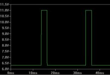
Now, here is the gate voltage on M1.
the big spikes are when V1 goes below a certain voltage and even if M1 is fully conducting it still will not maintain voltage on C1 - not a problem for me.
My problem, however, is with the gate voltage of 6.3v! It shouldn't stay at that level. Instead, it should go from negative rail to positive rail there.
It seems the comparator side of the circuitry isn't working. Why? maybe I should use a single voltage comparator rather than an opamp?
Your comments appreciated.
I got it working.
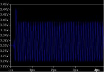
the dual-supply of the opamp I used is the problem. Once I drop'd in a single supply comparator (in this case, lt1720), and set the negative supply to zero (to make it single supply), the output stays in a very narrow band of 3.24v - 3.39v. M1 turns on and off at about 8 times per 1us (8Mhz?), for a C1=1uf, and R=2. the inrush current on C1 tops at 20amp.
Higher C1 value would tricker "matrix singular" errors (why?).
I think the next step is to figure out a way to control the frequency at which M1 switches on and off.
the chart below is the voltage over C1.
Attachments
the singular matrix error is caused by a (perfect) C1. once I dropped in a resistor to simulate ESR (40mohm), it works fine.
I also put a gate stopped on M1. Not much impact but the circuitry now works well, with one exception: it works at very high frequency and I am afraid that Rds in the MHz range could be a little too much.
Any suggestion on how to control the frequency?
Now, with a 47uf C1, 40mohm ESR and 2ohm R1, voltage on R1 goes from 3.29v to 3.31v. and it worsens to 3.28v to 3.31v when R1 goes down to 1ohm.
one other limitation of the circuit is that the voltage on R1 is limited by the maximum output on the comparator, minus Vgs on the MOSFET. In this case, it maxed out at 6v.
I got it resolved, 🙂
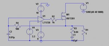
Putting a small RC network on the feedback loop lowers the frequency at which this whole thing works. The particular combination presented below allows the MOSFET to work at 2Mhz, and voltage on R1 to be roughly with 15% of regulation (from 3.15v - 3.65v).
comments welcome.
Putting a small RC network on the feedback loop lowers the frequency at which this whole thing works. The particular combination presented below allows the MOSFET to work at 2Mhz, and voltage on R1 to be roughly with 15% of regulation (from 3.15v - 3.65v).
comments welcome.
Hi Millwood,
I had the impression that you wanted to use a MOSFET as a diode with very low voltage drop for a power supply. Could be part of a bridge. In that case you have to turn on the FET during 50% of a mains cycle, e.g. by using (floating) comparators and optocouplers. This would reduce the loss that you normally get with a diode bridge.
Now I see that you built a kind of inductorless switched mode regulator, which is something completely different. I also think it is not going to work properly either. The circuit is actually a more or less regular voltage regulator that is oscillating (i.e. not stable). You can either change it into a linear regulator or include a coil and flywheel diode and make it a buck regulator.
Steven
yes, Steven. It is an oscilating regular, and made so by design.
the comparator and the R/C network form a crude VCO, and the MOSFET is the switch, and the capacitor is a filter.
it is closer to a switching ps than a linear ps.
the comparator and the R/C network form a crude VCO, and the MOSFET is the switch, and the capacitor is a filter.
it is closer to a switching ps than a linear ps.
But without the efficiency of a switched mode regulator! The MOSFET regulates on the edges instead of really being switched on and off. If it is switched on, there is no inductance to limit the charging current.
Steven
Steven
steven, the mosfet is fully on and off. and the inrush current is limited by the ESR of the cap - not a particularly good design, I would admit. I think you can alternatively put an inductor on the source of the mosfet.
I am starting to think that a bjt here may be a better choice because of its low loss of voltage.
I am starting to think that a bjt here may be a better choice because of its low loss of voltage.
Hi,
Yes, I think so too.....
Cheers,😉
I am starting to think that a bjt here may be a better choice because of its low loss of voltage.
Yes, I think so too.....
Cheers,😉
- Status
- Not open for further replies.
- Home
- Amplifiers
- Solid State
- Hexfet as diodes?