Hi
I was wondering if you guys could help me out ..
I'm trying to mod my Shanling CDS-100 ...it's a same player as the Music Hall CD-25..
This is what I did to it so far...new solid copper RCA outs , silver wiring , replaced the op-amps for 627 , sound coated the beast...
Player still has bleached sound with no dynamics and slow...just like the reviewer on 6moons audio said...song walks knee deep in water lol.
I found on the web Level 1 and Level 2 ( clock change ) mods for it...bad news ...they are charging arm and a leg for them ...could not find any schematics , instructions or parts list for them..
Do you guys have any advice ( besides buying a new player lol )?
Any help be greatly appreciated...
Thanks
daRRski
daRRski said:
I was wondering if you guys could help me out ..
I'm trying to mod my Shanling CDS-100 ...
Player still has bleached sound with no dynamics and slow...just like the reviewer on 6moons audio said...song walks knee deep in water lol.
daRRski
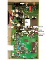
The Shanling may be knee deep in water but that does not mean it's hopeless.If you can post a close up photo of the dac/IV section leading to rca would be most helpful.Another complete overhead shot of the Shanling as well.We will learn together to tweak this baby. 😀
EDIT-- Keep photo size in the 80K - 100Kbytes.
Hi
Thanks for the reply ....
Here is some stuff I found on the mod for this player ...it might be better than the pictures .....
http://www.6moons.com/audioreviews/musichall/cd25.2.html
It showes the before and after the mod ...the problem is ...what parts are used ...specs and so on...
here is a little bit on it too..
http://www.6moons.com/audioreviews/musichall/cd25.html
little info on parts ..without specs..
"...Here's the menu of the PartsConnexion Level 1 mod as it pertains to the CD-25: Two sheets of Soundcoat inside the chassis (these work - the usual boinnng to the top plate goes thonk now); 4 EAR compliant Sorbothane isolation footers; 1 pair of Vampire OFC copper body, gold-plated RCA jacks; 2' of DH LABS pure silver, Teflon dielectric output wire; 10 x Japanese Riken Ohm ½ watt Carbon resistors with gold-plated leads in signal path; 8 x Black Gate Standard N- and C-grade electrolytic capacitors around the coupling caps and power supply; 2 x Multicap PPMFX-grade, metallized polypropylene capacitors in the signal path; 8 x SF4007 Vishay-Telefunken diodes added to bias supply; TRT Wonder solder throughout; ..
Replacing the caps and resistors might be easy....the problem would be figuring out how to ad ".8 x SF4007 Vishay-Telefunken diodes added to bias supply"..again...don't have any schematics..
Hope that helps...
thanks again for the reply ..
daRRski
Hi,
If you have used OPA627 then the Shanling should not be walking in water. 😀 Although you did not do all the mods.After looking at the board, it's obvious you can't do anything about the IV stage;it's like Marantz's HDAM ( discrete components).Unless you want to use your own and bypass it.
Here is what I think:
Do it in stages so you can evaluate if there are any changes to the sound.
1. SF4007 diodes.( DC rectifier).I don't recommend them.The reviewer looks like he's related to Sonic Frontiers.The diodes are fast but not fast enough.Try FR107s or Schotky diodes 100V should be enough.For the real deal try SBYV27-100 or 150 soft recovery diodes ( reduced RFI emission).
2. The 2X Multicap ppmfx-- you can choose others if you like.
3. The riken resistors-- I count 8 but the other 2 may be covered by white arrows.These are optional.(I don't think it's needed).
4. Try 1 + 2 and then do the power filter and decoupling caps.Again stage by stage.
Hope this is enough for you to start modding.The picture is self explanatory.
Attachments
Hi
Sorry to bug you again....I'm kinda new at this lol..
When replacing the caps I have to find out the original uF and DC V and match it with multicaps ..right ?
With rectifiers ...there is orientation they have to go in ...on my old ones ...can't find any markings ... ...
...
Thanks for your help...and patience...like I told you ...I'm a total noob ...lol
Thanks again
daRRski
Sorry to bug you again....I'm kinda new at this lol..
When replacing the caps I have to find out the original uF and DC V and match it with multicaps ..right ?
With rectifiers ...there is orientation they have to go in ...on my old ones ...can't find any markings ...
...Thanks for your help...and patience...like I told you ...I'm a total noob ...lol
Thanks again
daRRski
Hi,
Look at the marking on the body of the diodes if there are no silkscreen markings like + or - on the pcb.The white band is the cathode or minus sign.So mark a plus or minus on the pcb with a permanent marker at the appropriate end or better take a close up of all relevant section you wish to mod( before you attempt to remove),you get the idea, right?
The 2 pcs. multicap (white colour) are non or bipolar so no need to observe polarity( original are orange in colour in the left picture).The other electrolytic caps are another matter.ALWAYS note the correct polarity by marking again before removal.Of course take note or write down the cap designation like C1 =??UF ??V before hand.
The resistors are colour coded so you need to know the system coding to decypher the value.
Feel free to ask questions as this is your player.You should do it in stages and not rush.Others will learn from you.The E caps may need to increase in capacitance some may need to reduced.So read all about this issue regarding voltage regulators. before proceeding.Also the type to substitute.That's why a schematic is useful.If you are systematic and do the right thing it can be rewarding.Good luck.
Hi
I realy appreciate your help...thank you very much ...and I'm learning a little lol..
I do have a hard time locating the SBYV27...it would take around 30 days lead time to order set ...
What do you think about using those instead ..
https://www.cree.com/products/pdf/CSD01060.G.pdf
the TO-220-2.. ???
In specs they have faster recovery time than SBYV27.
The question that I have is with replacing bipolar with unipolar rectifiers ...would that work in my set up ?Anything I have to watch for when installing those ?...Finally should I go for those..or wait for the SBYV27 ?
Thanks again
daRRski
Hi,
The Schottky diodes can be used but first let's clear up the confusion about "bipolar/unipolar" in the datasheet.It's not wrong to say as such if you understand the differences between normal diodes and schottky types.In our case we will treat all as a diode that will conduct in one direction only.So watch the polarity
RFI ( radio frequency interference) is generated as the diodes abruptly switch off Normal rectifier (1n400x) are alot slower so the window/time period is longer,hence more RFI.Schottkly diode has "no" switch off time,almost instantaneous nevertheless it's still an abrupt switch off so there is RFI.Soft recovery diodes have a gentlier slope/switchoff/recovery time but alot faster hence less RFI.A proven way is to parallel a small capcitor about 0.01 -0.1uF across the doide to slow down the rate of change.
There have been good results reported over the years about schottkys used in tube amps and mods, still the matter of subjectivity shows up so you may like what you hear or not.It'really your choice,personally I have not tried schottkys so I can't comment.Subjectively for SBYV27 I will say it's feels quieter and overall enhances the sound to be less digital.There it is politically correct. 😀
Hi
Thank you sir...I guess I will have to wait for the SBYV27s 😀
And thanks again for all you help and info...
daRRski
Thank you sir...I guess I will have to wait for the SBYV27s 😀
And thanks again for all you help and info...
daRRski
Hi
Sorry to bother you again ...but need some more help.
Still waiting for my rectifiers , apparently they are on back order.
This one is totally different issue.
Just got a tube amp...
http://www.chinese-hifi.co.uk/Mingda meixing/?sortby=7
Meixing Ming-da MC34-AB from Ornec .
Problem is , that eveytime I switch the thing on is blowing a fuse on the external power supply . Fuse is located on the IEC socket .
Any ideas what could cause that ?
Didn't get any responce from factory , and the last one from Ornec told me to change the fuse lol
Thanks
daRRski
Hi,
Mingda MC34-AB has a international AC voltage switch, did you switch to correct ACV for Canada? If switch is correct then check if fuse rating is right one which would be double of 220V whatever that is. Now if both items checks out then I think the external power supply is faulty.Since it's brand new,you should bring it back to the shop for resolution of this problem.What is AC voltage for Canada btw?
Good luck.
Hi
Thanks for a fast reply ...the switch was set to 110V..that's what we have here in Canada.The fuse used is a 3A 250V.
I did try couple more...they all blow as soon as you switch it on.Do you think that is the power supply , not the amp causing it ?
Thanks
daRRski
Thanks for a fast reply ...the switch was set to 110V..that's what we have here in Canada.The fuse used is a 3A 250V.
I did try couple more...they all blow as soon as you switch it on.Do you think that is the power supply , not the amp causing it ?
Thanks
daRRski
daRRski said:Hi
Thanks for a fast reply ...the switch was set to 110V..that's what we have here in Canada.The fuse used is a 3A 250V.
I did try couple more...they all blow as soon as you switch it on.Do you think that is the power supply , not the amp causing it ?
Thanks
daRRski
Hi,
If the original fuse is 3A 250V then it's probably meant for 220V use.Like I said earlier ,the rating should be about 2X for 110V.Please check with the shop to confirm if fuse rating is correct or not.
Mingda MC34 is 8X EL34 tube at 3A ? Assume only 1 transformer?.
I have schematic for 4X EL34 for Japan voltage at 100V the fuse rating is 5A 125V.
 1 transformer.
I feel the fuse rating is wrong.Please use specified voltage rating for your country.
EDIT--- All this maybe different if power supply is switchmode instead of linear.Then rating maybe less but would mean supply is faulty.Do tube amps use switchmode anyway?
- Status
- Not open for further replies.
- Home
- Source & Line
- Digital Source
- help ...