Hi,
My sad story starts with a complete rebuild of a Wurlitzer 1400 jukebox - all done and restored, but I'm not happy with the audio quality - it sounds hollowed out, like missing the mid-range. The previous owner had the amp "professionally restored" and it does look like it was done by someone who had done this before. I did notice that none of the resistors had been replaced so did a test and found most were pretty far out, so replaced those. I also tried different tubes, different cartridges, and several other easy things before breaking out the scope.
I've not done a ton of work on tube amps, so there is a possibility that this is working exactly as designed, but I don't think so. I used a sine wave at a constant Vrms input of about .7v after the coupling cap after the first tube that deals with the Wurlitzer Cobra carts. This is comparable to what I see there when I play a record. Then measured the output on the dummy load, calculate the gain, and plot a frequency response curve. What I'm seeing is a signal with peaks at about 40hz and 3Khz that drops off fast above and below and sags way down in the middle with a low at about 500hz. This seems pretty consistent with how I'm interpreting the output. Plenty of bass, highs are there, plenty of volume, but not much in the middle.
So, I traced through the amp and the response is much more flat from there, through the first 6SJ7 and up until the output of the first 6SN7 that I understand is configured as a cathode follower. From there the signal goes into a choke and resistor in parallel and then splits with two caps into the two volume pots, bass pot and assorted passive components (the treble pot is at the input to the cathode follower). I've double checked all of the wiring, the values, and the measurements of these components and everything seems to be good. The only thing that I question is that the 6SN7 cathode is measuring 37VDC and the schematic shows it as 3.5VDC. The plate is a little high (262V vs the schematic of 250V). I did disconnect everything from the output and measure the AC signal there and it does not have that strange big dip - I only see that on the output when it's connected downstream.
I'd really appreciate any help - I am happy to attach pictures, plots, or take more measurements. I'd really like to beat this thing!
Thanks,
-Steve.
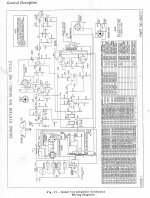
If you have a clean image of the schematic, that would be super helpful. The ones I see online are so blurry they are pretty much illegible.
A schematic would be great but isn't the 6sn7 part of the phase splitter for the output stage. Not sure without a circuit.
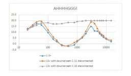
Thanks in advance!!! Attached is a scan of the schematic. I'm new to this forum, so hopefully I'm doing this right. I also attached a picture of some of my measurements. It's been a REALLY long time since I've built a plot like this, so I'm hoping I did it correctly. It includes a plot of what the AC coupled signal looks like at the downstream side of L-3. I also tried measuring at the same spot when C-10 is disconnected and when C-11 is disconnected.
Attachments
Oh, and to JonSnell - yes, half the 6SN7 is used for the phase splitter, but the other have is used in the preamp section before the volume/bass controls.
Looks like a loudness control combined with the volume but in the wrong direction.
Try conneting the ground to the other end of R45.
Mona
Try conneting the ground to the other end of R45.
Mona
It sure looks like that jukebox employs a magnetic cartridge of some kind. That means RIAA playback equalization is being applied to the I/P signal. In order to perform valid "sweeps", what comes from the signal generator has to be passed through a reverse RIAA network, like this.
Hi Mona, R-45 is wired so that it's at zero ohms with the volume at min and increases with increased vol. I've got it set at about 11:00, which equates to about 1K on this pot. The ganged R-46 pot of the volume control is also zero ohms at min volume. I guess I'm not following you. Are you suggesting R-45 should decrease in resistance when increasing vol and that both the schematic and the factory wiring are wrong?
Hi Eli, The Zenith Cobra is actuallya variable capacitor next to a coil. This is part of an oscillator circuit. Not really a ceramic or magnetic. Thestylus is mechanically coupled to a disk that is the variable part of thecapacitor. Its movement modulates the oscillator's frequency which is thendemodulated into audio. This is why I injected the signal after the first tube - to take the cartridge out of the equation. But are you saying that my response looks the way it does so as to compensate for the RIAA? I understand that ceramic carts do this inherently, but not sure about Cobra. I also wondered if that was the purpose of the components immediately following the input tube before the first amplification stage.
Hi Eli, The Zenith Cobra is actuallya variable capacitor next to a coil. This is part of an oscillator circuit. Not really a ceramic or magnetic. Thestylus is mechanically coupled to a disk that is the variable part of thecapacitor. Its movement modulates the oscillator's frequency which is thendemodulated into audio. This is why I injected the signal after the first tube - to take the cartridge out of the equation. But are you saying that my response looks the way it does so as to compensate for the RIAA? I understand that ceramic carts do this inherently, but not sure about Cobra. I also wondered if that was the purpose of the components immediately following the input tube before the first amplification stage.
Hi Eli, The Zenith Cobra is actuallya variable capacitor next to a coil. This is part of an oscillator circuit. Not really a ceramic or magnetic. Thestylus is mechanically coupled to a disk that is the variable part of thecapacitor. Its movement modulates the oscillator's frequency which is thendemodulated into audio. This is why I injected the signal after the first tube - to take the cartridge out of the equation. But are you saying that my response looks the way it does so as to compensate for the RIAA? I understand that ceramic carts do this inherently, but not sure about Cobra. I also wondered if that was the purpose of the components immediately following the input tube before the first amplification stage.
Hmmm, it seems Zenith "borrowed" Weathers' FM capacitance idea. That technology has an amplitude response, unlike the velocity response exhibited by magnetic cartridges. The RIAA playback function accounts for both the noise limiting HF boost added at master cutting time and the velocity vs. amplitude discrepancy. Weathers made extraordinarily light weight stuff and the mechanical damping of HF boost exhibited by piezoelectric cartridges is, according to my hunch, absent. Therefore, some adjustment to the "raw" signal seems in order, but it will be quite unique. Study the schematic closely and look for frequency shaping "elements".
That device I previously linked will not be useful here. It's intended for use with commonplace mag. cart. equipment.
All that stuff around the volumes/bass pots IS a serious response-shaping network.
And it probably is different for every setting of the pots. R45 is clearly to Q-up the 680Hz dip. It seems to drop mids faster than "overall gain". If it is "too loud" (interfering with conversation), the mid is dipped more than lows/highs. The music still plays(pays) without drowning the conversation.
And it echoes what I remember of older jukeboxes. BASS (not deep bass). Highs. And a notable lack of midrange, because a tavern was NOT about the music but about the conversation.
I'm not going to sim this but someone may.
Attachments
Last edited:
No, that's the right way.Hi Mona, R-45 is wired so that it's at zero ohms with the volume at min and increases with increased vol. I've got it set at about 11:00, which equates to about 1K on this pot. The ganged R-46 pot of the volume control is also zero ohms at min volume. I guess I'm not following you. Are you suggesting R-45 should decrease in resistance when increasing vol and that both the schematic and the factory wiring are wrong?
Because of "The previous owner had the amp "professionally restored" "
it seems not impossible someone had made a wrong connection.
Mona
Thanks! I'm thinking I may just add a switch to remove R45 to get back to a flatter response. I guess I thought the tone controls would have been adequate to reduce the mids if a tavern wanted to do so, but???
Any thoughts on my 38V on the 6SN7 cathode vs. the 3.5V on the schematic? With the 38V I'm calculating about 6ma of current through the tube. I'm not great reading tube data sheets, but that doesn't seem out of line. Could the schematic be wrong and suppose to read 35V? At 3.5V that would be more like 0.6ma.
Thanks,
-Steve.

Moost probable is the 3V5 is over R15 and that R16 is 47k not 4.7k
Another case of mixup dot/stain, when will you folks write 4,7 and not the error prone 4.7 😱
With R16=47k the cathode comes up to 105V, normal for a cathode follower.
If the cathode is on only 35V the tube is bad or the anode voltage isn't 250V but much lower.
Mona
Another case of mixup dot/stain, when will you folks write 4,7 and not the error prone 4.7 😱
With R16=47k the cathode comes up to 105V, normal for a cathode follower.
If the cathode is on only 35V the tube is bad or the anode voltage isn't 250V but much lower.
Mona
Attachments
Last edited:
Very nice! Looks just like my measurements. But please help me understand the different curves - what's varying with each color?
Moost probable is the 3V5 is over R15 and that R16 is 47k not 4.7k
Another case of mixup dot/stain, when will you folks write 4,7 and not the error prone 4.7 😱
With R16=47k the cathode comes up to 105V, normal for a cathode follower.
If the cathode is on only 35V the tube is bad or the anode voltage isn't 250V but much lower.
Mona
Hi Mona! Hmmm the schematic is pretty clear that 4.7 (4,7)k and 1.2K are the values intended. I also happen to have another W1400 514 Amp that is all rusted out, but good for reference. It too is clearly is using 4.7K and 1.2K here. I've tried three different tubes and get the same 38V at the cathode where the schematic says it should be 3.5V. I have 262V at the plate and see 22.4v at the grid.
Very nice! Looks just like my measurements. But please help me understand the different curves - what's varying with each color? Is this increases in the ganged volume pots? Assuming so, I guess I can see why the tone controls alone won't achieve the same result. I guess the idea is to drop the mids more at lower volumes and increase at higher volumes. I guess that makes some sense to enable room conversation more at lower volumes, but for home use I'd like to have reasonable mid response at lower volumes. I'm thinking that adding that switch to disable R-45 will do what I need.
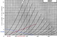
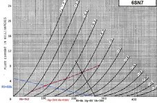
I put the data you provide in the 6SN7 grafics and it is possible but rather strange loadline.Hi Mona! Hmmm the schematic is pretty clear that 4.7 (4,7)k and 1.2K are the values intended. I also happen to have another W1400 514 Amp that is all rusted out, but good for reference. It too is clearly is using 4.7K and 1.2K here. I've tried three different tubes and get the same 38V at the cathode where the schematic says it should be 3.5V. I have 262V at the plate and see 22.4v at the grid.
The -Vg=8V so there is 30V on the grid (and on R16), you lose 7,5V on the 1M by the meter current and read 22,4V.
I made an error stating Vk= 105V with 47k for R16, used to anode load I inverted the deduction, it's more like Vk=150V.
With the resistors as is, the gain of the cathode follower is ~0,89 and with R16=47k you get ~0,93.
Mona
Attachments
All that stuff around the volumes/bass pots IS a serious response-shaping network.
And it probably is different for every setting of the pots. R45 is clearly to Q-up the 680Hz dip. It seems to drop mids faster than "overall gain". If it is "too loud" (interfering with conversation), the mid is dipped more than lows/highs. The music still plays(pays) without drowning the conversation.
And it echoes what I remember of older jukeboxes. BASS (not deep bass). Highs. And a notable lack of midrange, because a tavern was NOT about the music but about the conversation.
I'm not going to sim this but someone may.
Thanks PRR - any help on what the different plots represent? Are these different volume levels?
Thanks! I got some feedback from a jukebox amp expert and he does think the 3.5V is wrong and should be 35V, which is about what I'm seeing. The gain for cathode followers as I understand it, is indeed less than unity (which I'm also seeing) as the primary purpose is to convert impedance. So, I think this part of the circuit is acting as designed.I put the data you provide in the 6SN7 grafics and it is possible but rather strange loadline.
The -Vg=8V so there is 30V on the grid (and on R16), you lose 7,5V on the 1M by the meter current and read 22,4V.
I made an error stating Vk= 105V with 47k for R16, used to anode load I inverted the deduction, it's more like Vk=150V.
With the resistors as is, the gain of the cathode follower is ~0,89 and with R16=47k you get ~0,93.
Mona
- Home
- Amplifiers
- Tubes / Valves
- Help with Wurlitzer 514 Amp