Hi. I have a Rod Elliot low voltage power supply that needs 16v ac. I have a wall wart psu suitable for turntables giving 16v ac. The connections on the wall wart do not specify neutral or ground, checked with meter I get identical readings whichever way meter connected.
The connections on the power supply board to which I want to connect the wall wart output plug are marked as AC and ground.
Can anyone tell me how to find which is ground and which live on output of wall wart. I only have a digital meter.
Thanks
Mike
The connections on the power supply board to which I want to connect the wall wart output plug are marked as AC and ground.
Can anyone tell me how to find which is ground and which live on output of wall wart. I only have a digital meter.
Thanks
Mike
wall wart info
Hi Andrew.
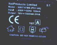
Thanks for reply, wall wart does have double concentric squares symbol.
Regards
Mike
Hi Andrew.
Thanks for reply, wall wart does have double concentric squares symbol.
Regards
Mike
Good, that means you don't need to add in a Protective Earth.
It also means the two outputs from the wall wart are isolated. Neither are connected to Mains Live, nor to Mains Neutral, nor to Mains Earth.
You have two wires that are connected internally to an AC voltage source. The two wires both have AC on them.
These should connect to two pads with ~ and ~ marked on them, or maybe AC1 and AC2
There should not be a ground symbol for either wire connection.
Can you show a pic? Either your own, or to a site that shows a pic?
Last edited:
A square symbol within another square symbol means Doubly Insulated and does as Andrew states have no connection to the supply and by default is isolated from the mains supply.
wall wart from Mike Noble
Hi.
I am enclosing 2 images. However if they do not come through this is the instructions
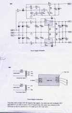
for connecting supply. ' With a single 16V AC input to the supply, you must use only
terminals AC2 and GND '
The actual connections are marked on circiut board AC1, AC2, GND.
Thanks
Mike
Hi.
I am enclosing 2 images. However if they do not come through this is the instructions
for connecting supply. ' With a single 16V AC input to the supply, you must use only
terminals AC2 and GND '
The actual connections are marked on circiut board AC1, AC2, GND.
Thanks
Mike
Attachments
I see what they have done.
that GND is actually the pad for the transformer centre tap. It should have been labelled CT
A three wire centre tapped secondary uses the two AC and the centre tap.
A dual secondary with four wires uses AC1 and centre tap for one secondary and AC2 and centre tap for the other secondary. BUT !!!!! you must use a protection device in case the phase of the two Secondaries gets mixed up. A Mains Bulb Tester is a good protection device.
A single secondary uses the half bridge as a full wave rectifier. This is not a good way to wire this up.
Buy a dual secondary, or a centre tapped transformer, or buy a second double insulated transformer to match the one you have.
Why did you wait so long before you posted that info?
Last edited:
SHORT answer: you can NOT use that wall wart to supply that circuit, period.
Sorry.
You need a:
16+16VAC center tapped transformer
Don´t know your ??preamp?? current consumption, please state it so we can suggest a transformer current or VA rating.
Sorry.
You need a:
16+16VAC center tapped transformer
Don´t know your ??preamp?? current consumption, please state it so we can suggest a transformer current or VA rating.
wall wart mike noble
Hi.
Thanks to all for info.
Delay in posting pics due to not using PC on regular basis.
Regards.
Mike
Hi.
Thanks to all for info.
Delay in posting pics due to not using PC on regular basis.
Regards.
Mike
SHORT answer: you can NOT use that wall wart to supply that circuit, period.
Sorry.
You need a:
16+16VAC center tapped transformer
Don´t know your ??preamp?? current consumption, please state it so we can suggest a transformer current or VA rating.
Non monsieur!
He possibly can use that wall wart, feeding an AC-input and AC return.
The rectifier will then work as voltage doubler resulting in twice the ripple.
Any way, it is worth a try!😉
It looks like a voltage doubler, but it is charging two separate series connected capacitors. That gives virtually the same voltage as using the whole bridge rectifier from a centre tapped transformer.Non monsieur!
He possibly can use that wall wart, feeding an AC-input and AC return.
The rectifier will then work as voltage doubler resulting in twice the ripple.
Any way, it is worth a try!😉
It is a full wave rectifier, not a voltage doubler.
As per Rod Elliott's project page Power Supply for Preamps - "If a single AC supply is connected between GND and AC2, the rectifier is a full-wave voltage-doubler type, and with an input of 16VAC will provide about +/-20V DC at a current of up to at least 100mA - this should be enough for the most power-hungry preamp."
It does not matter which way round the 16VAC is connected. Ignore the naysayers.
It does not matter which way round the 16VAC is connected. Ignore the naysayers.
It's NOT a voltage doubler. The 16vac would have to series pass through a cap to make a voltage doubler.
I guess it isn't. With single supply you have half wave positive via D1 & half wave negative via D3. D2 & D4 do nothing and may be omitted.
Same as Project Phonobox and it will work.
I suggest you tell Rod - he does respond to email and will appreciate the interest in his projects.
Same as Project Phonobox and it will work.
I suggest you tell Rod - he does respond to email and will appreciate the interest in his projects.
And here is the correct answer.
You CAN use your wall wart. Connected to ac2 and gnd the circuit acts as as half wave voltage doubler. Its all explained clearly on the ESP p05 article.
You CAN use your wall wart. Connected to ac2 and gnd the circuit acts as as half wave voltage doubler. Its all explained clearly on the ESP p05 article.
The circuit is simply two half wave rectifiers, one producing a positive rail and one a negative.
Its only a 'voltage doubler' if you decide to move your measurement point of reference to one or other of the rails.
Fwiw, the circuit is the same in outline as that used in the 02 headphone amp.
Its only a 'voltage doubler' if you decide to move your measurement point of reference to one or other of the rails.
Fwiw, the circuit is the same in outline as that used in the 02 headphone amp.
Attachments

The circuit is simply two half wave rectifiers, one producing a positive rail and one a negative.
Its only a 'voltage doubler' if you decide to move your measurement point of reference to one or other of the rails.
Fwiw, the circuit is the same in outline as that used in the 02 headphone amp.
Yessir. This summarizes this more ore less useless discusion.😉
- Status
- Not open for further replies.
- Home
- Amplifiers
- Power Supplies
- help with wall wart ac/ac power supply