Hello all, I've recently taken on what is for me a somewhat advanced project...a rebuild of an ST-70 with an upgraded kit with auto-bias. Not VTA but similar.
I have hum in both channels. Very messy signal on oscilloscope. Multimeter Hz reading shows 60 Hz but bounces around it a fair bit.
I have entirely removed the wires between the RCA input and the PCB and it made no difference. But at least I guess that means I ruled out its coming from the input. When the RCA was connected, hum was still there when RCA shorting plugs were used.
I have also "unbundled" various wires that were running next to each other to make the wiring look neater, but moving that stuff around also makes no difference.
I have used two entirely different sets of tubes and it made no difference.
I plugged it into a PS Audio power regenerator that theoretically creates an absolutely clean AC sinewave and that made no difference.
If I put my ear near the power transformer, I do hear a constant hum that I think is 60 Hz. It's louder for the first few seconds and then drops down to a lower but constant level.
At this point, the level of knowledge required for troubleshooting has exceeded my expertise and I'd be extremely grateful for any help.
Best,
Ross in Denver

Always short each input when checking for noise.
Probably best to remove the auto bias and go on from there.
Probably best to remove the auto bias and go on from there.
The company that provides the kit does not offer the schematic (in order to protect their intellectual property.)
Removing the auto-bias would be a massive undertaking...but if I end up unable to solve without trying that then I will figure out how to do it.
Removing the auto-bias would be a massive undertaking...but if I end up unable to solve without trying that then I will figure out how to do it.
Sorry for your dilemma. How about posting some good photos. At least that will tell the tube complement and perhaps topology. Perhaps some help or ideas could be forthcoming.The company that provides the kit does not offer the schematic (in order to protect their intellectual property.)
With a hum unrelated to inputs suspicion goes to the power supply first. Photos of the power supply will be helpful too. Have you checked all the capacitors (especially those in the bias supply) for correct polarity? Scoped the ripple on supplies?
Hi Francois, will post pics soon but all the relevant and available info is here...important stuff (with pictures) starts on page 11, I think: https://milleraudiollc.com/wp-content/uploads/2025/01/Dyna_70_Auto-Bias_Assembly-Manual-v1.1.pdf
Basically impossible to put caps in backwards because they all go with the line/arrow indicating the negative lead facing the back of the board.
Not sure how to "scope the ripple"! (I don't have much experience with oscilloscopes but happy to try whatever you tell me to try.)
Basically impossible to put caps in backwards because they all go with the line/arrow indicating the negative lead facing the back of the board.
Not sure how to "scope the ripple"! (I don't have much experience with oscilloscopes but happy to try whatever you tell me to try.)
I should add...I agree that this almost has to be somewhere in the power supply because the input RCA jacks are disconnected from the circuit and the hum is approximately equally loud in both channels.
Here's a crazy question. Is there any chance that putting the power transformer back together even very slightly "wrong" after painting the bell ends could cause this?
Here's a crazy question. Is there any chance that putting the power transformer back together even very slightly "wrong" after painting the bell ends could cause this?
OK, I should know the answer to this but I'm just learning this stuff: How do I measure the bias voltage for the 6CA7 power tubes? Is it as simple as measuring one particular pin (vs ground)? I'm told it should be at least -55V. Grid 1 is pin 5...but I see 3 grid connections. Sorry for the newbie questions.
It's about time for the diyAudio community to speak up about this BS. Why don't we speak out against this foolishness? Name and shame the folk who try to pretend that a schematic is some kind of secret sauce. What brand name is this kit? Or, would they rather that their name be secret too?The company that provides the kit does not offer the schematic (in order to protect their intellectual property.)
All good fortune,
Chris
For what it's worth, Chris, I don't blame them. If they have a superior kit (and it's not made less superior by some potential error I made), I don't think they should feel required to share the schematic that they spent years developing. I understand that it makes my current problem harder to solve, but if I were in their position I think I'd do what they're doing. Especially given what the Chinese will do with such schematics.
If someone wants to steal intellectual property, they can just buy one and copy it.
Having the schematic available does not change anything.
Having the schematic available does not change anything.
Hi,
Attached it is a link that have the schematic for the ST70 with pictures.
http://diyaudioprojects.com/Schematics/Dynaco-ST70-Tube-Amp-Schematic.htm
Attached it is a link that have the schematic for the ST70 with pictures.
http://diyaudioprojects.com/Schematics/Dynaco-ST70-Tube-Amp-Schematic.htm
I looked up the Miller Audio assembly manual. Their “Ultimate” appears to be a derivative of Roy Motram’s 6SN7 Mullard design with Pavel’s Audioamp adaptive bias board added. If they are unwilling to publish the schematic I assume they will offer help to their customers to track down issues of your sort.Hi Francois, will post pics soon but all the relevant and available info is here...important stuff (with pictures) starts on page 11, I think: https://milleraudiollc.com/wp-content/uploads/2025/01/Dyna_70_Auto-Bias_Assembly-Manual-v1.1.pdf
Basically impossible to put caps in backwards because they all go with the line/arrow indicating the negative lead facing the back of the board.
Not sure how to "scope the ripple"! (I don't have much experience with oscilloscopes but happy to try whatever you tell me to try.)
It might be helpful to look at Roy’s octal driver PCB here: https://www.tubes4hifi.com/ST70.htm. If Miller Audio does not have a discussion board where you can ask questions I suggest that you check out the sources for tubes4hifi here: https://dynacotubeaudio.forumotion.com/t4156-pavel-s-auto-bias-board
It appears Miller buys or licenses the adaptive bias boards from Pavel, because they look identical. I suggest you take a look at Pavel’s website because he has some hookup diagrams in his installation manual that lacks in the step-by-step Miller manual. It also provides instructions for presetting the bias levels that Miller has already done for you, but you could check that it it is still at the correct setting.
https://www.audioamp.eu/automatic-b...i-st70-st120-v2-0-with-isolation-transformer/
I agree that the Miller PCB seems to guide the correct orientation of capacitors, but I have personally soldered negative bias caps incorrectly, since they are “reversed” from other HV caps where the “minus” goes to ground. I could not make out in the manuals photos where the bias caps are located.
Could you confirm that you have done the steps listed on page 23 in the Miller Audio manual you posted about “Checking the auto bias level and B+ with tubes” and measured the correct voltages in your amp?
What I meant by scoping the ripple in the B+ is hooking up your oscilloscope to the B+ supply (with proper attenuation to protect the scope from overvoltage) and check what ripple you have remaining after your PS filtering. That would give you a measure of how well your powers supply is working.
If you don’t know how to check the bias, plate current and other parameter on the sockets of EL34 tubes I suggest that you go to YouTube and watch some videos on the topic while having the basing diagram ready that shows which tube elements are connected to which pins on the socket. See here: https://frank.pocnet.net/sheets/030/e/EL34.pdf The pins are as seen from underneath the amplifier.
As always, regardless of experience level, be cautious and beware, some of the voltages inside are LETHAL.
Good luck.
Last edited:
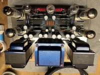
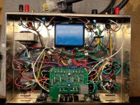
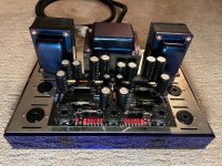
Attached are pictures of the amp. In the photo of the internal wiring, note that the long "s-shaped" white wires connecting the RCA jacks to the circuit board have been removed (to rule out the RCAs and that wire as the source of the noise.)
Attachments
- Home
- Amplifiers
- Tubes / Valves
- Help with ST-70 variant hum in both channels