Hi,
I have tried to simulate the behavior of a loudspeaker. For that I have used the model from Micka (http://micka.de/org/en/download/spice-tsp_en.pdf).
For comparison, I've resorted to Kyle's Lahnakoski versions (Driver Analysis).
All things the results are not in the approach similar to the above in the published sources.
My question to the experts here: What's going wrong?
I am currently at a loss.
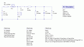
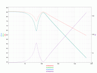
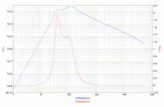
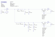
The first two pictures are the simulation of a speaker without box with qucs and the result.
The next four pictures are the simulation of a bass reflex box and the results.
Greetings
Steffen
Attachments
But I think I've found the error:
In the simulations I did Le = 0.47 * 10e-3, which is interpreted by qucs not as expected.
If I do Le = 0.47 * 10 ^ (-3) or set Le = 0.47 * 0.001 then the results are plausible and are consistent with those of Micka.
The current in the 2.7 uF capacitor accordingly corresponds to the course of sound pressure.
Some "play" with the parameters of the box then shows the curves that result with other box-simulations and other publications.
Greetings
Steffen
So, I got it 😉
Attached is a zip-file with a qucs-library for loudspeakers (just loudspeaker, closed box and vented box) and also a qucs-projekt with the schemes.
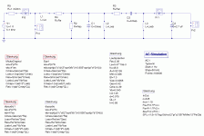
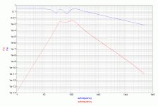
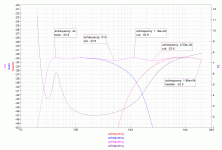
On the pictures is a 2-way-box simulation, just as example 🙂
Greetings
Steffen
Attached is a zip-file with a qucs-library for loudspeakers (just loudspeaker, closed box and vented box) and also a qucs-projekt with the schemes.
On the pictures is a 2-way-box simulation, just as example 🙂
Greetings
Steffen
Attachments
Hi,
This is great!
I have been trying to get a similar qucs model to work, also from the prior work by Micka. I'm wondering why the capacitors C4 & C1 are added ofter the driver output in the final version of your circuit? Where does the 2.7 uf value come from?
thanks
rob
This is great!
I have been trying to get a similar qucs model to work, also from the prior work by Micka. I'm wondering why the capacitors C4 & C1 are added ofter the driver output in the final version of your circuit? Where does the 2.7 uf value come from?
thanks
rob
- Status
- Not open for further replies.
