I found this balanced idea in the schematics of the fender sidekick series and I wanted to make it a pedal using the small accoutronics AMC2BF3 (those blue ones) 150ohms

First I simulated the idea, One opamp OPA2134 is enough to drive 150 ohms tank to 5Vrms so no need for paralleling opamps like in the side kick

I aimed for Single supply so the opamp are biased to 1/2 of power suppy
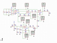
This is the final circuit with the Buffer and Mixer wich is bases in the Elliot ESP reverb.

The extra opamp is used to buffer the 6V vref, I aimed for this to be used with normal 9V power supplies. So the Voltage is boosted to 12V with a RO-0912 isolate power supply I have used those modules to increase voltage or to clean ground loops.
Well, the problem is that it that doesn't work. NO SOUND. Can you guy Help me to find if there is a problem with the design or should I be looking into Human error in the building process?
I Removed U2 and tested the buffer alone. That part seems to do something but Vol is reduced a bit so not a true buffer. After closing the jumper and trying to get something from the out, is mute.
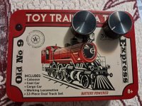
Here some pic if the enclosure


First I simulated the idea, One opamp OPA2134 is enough to drive 150 ohms tank to 5Vrms so no need for paralleling opamps like in the side kick
I aimed for Single supply so the opamp are biased to 1/2 of power suppy
This is the final circuit with the Buffer and Mixer wich is bases in the Elliot ESP reverb.
The extra opamp is used to buffer the 6V vref, I aimed for this to be used with normal 9V power supplies. So the Voltage is boosted to 12V with a RO-0912 isolate power supply I have used those modules to increase voltage or to clean ground loops.
Well, the problem is that it that doesn't work. NO SOUND. Can you guy Help me to find if there is a problem with the design or should I be looking into Human error in the building process?
I Removed U2 and tested the buffer alone. That part seems to do something but Vol is reduced a bit so not a true buffer. After closing the jumper and trying to get something from the out, is mute.
Here some pic if the enclosure
Attachments
Post a complete schematic with all the MEASURED node DC voltages marked.
The single supply arrangement must have a problem.
The single supply arrangement must have a problem.
Yeah Rayma you are right the Level pot must be sandwiched between two capacitors otherwise biasing voltage is going to ground.

Putting output bias to 9V-11V depending on the pot position

Adding a capacitor after the pot solve the bias problem.

I will test in the real board tonight
THANKS FOR THE HELP
Putting output bias to 9V-11V depending on the pot position
Adding a capacitor after the pot solve the bias problem.
I will test in the real board tonight
THANKS FOR THE HELP