I purchased this 2.1 preamp from Amazon to incorporate into a project I'm working on. I specifically need it to perform low pass filtering to send signal to a mono tpa3116 board. However as all other preamps Ive tried it doesn't filter out enough of the voices. Its supposed to be a 12db slope with adjustable frequency from somewhere around 20hz-200hz however even at the lowest setting it still allows allot of voices through. Is there anyway I can adjust/fix this board? I am good at soldering and have already played with the feedback loop of the stereo gain but can't figure out the bass circuit at all!
Circuit diagram
PCB
Would removing the potentiometer for the frequency adjustment and just fixing the LPF at 60-80hz at 12db slope be viable?
Circuit diagram
PCB
Would removing the potentiometer for the frequency adjustment and just fixing the LPF at 60-80hz at 12db slope be viable?
Last edited:
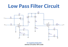
Is this your cross over? I had problems with the links. The sub is already 24dB/octave but it is at about 280Hz. There is no frequency adjustment in the schematic, just bass gain. Seems the board and schematic don't match. The schematic shows 5 dual op-amps and one pot. If it was the schematic then I recommend you change resistors R17, R18, R19, R20 to about 12K, but the board is completely different.

Last edited:
AHHH that explains why I am so confused! I thought I was just a bigger newbe than I thought and was understanding the diagram wrong. This is the PCB does that help? I don't have a pic of the bottom but 90% is on top.
Attachments
![Screenshot_20231205_234144_Samsung_Internet[1].jpg](/community/data/attachments/1161/1161604-aa052ce099042e31c71df7f132ad4ea0.jpg?hash=qgUs4JkELj)
Seems like this is from:
https://www.circuits-diy.com/subwoofer-filter-circuit-tl072-tl074/#Circuit_Diagram
but it may be more like
https://www.circuits-diy.com/low-pass-filter-for-subwoofer/
which is 12dB adjustable frequency, but again the photo of the board and the schematic do not match. With a dual pot for the adjustable frequency, larger caps could lower the frequency.
If you can find a schematic that matches what you actually have, then we can help.
PS: Sorry, I am not going to spend hours reverse engineering the photo of the PCB. If I find a schematic that matches, maybe I'll get back to you.
Last edited:
I can't find the real schematic for it I have searched for way longer than I should have. The link you posted may help me figure out how to raise the gain of the bass side so thank you. If I can raise the gain of the subwoofer opamp than I can at least make it usable and finish my project. As it is right now the line output voltage of the stereo pair is 1.6v while the mono is 400mv. I'd like to bump it up to at least 600mv minimum with closer to 1v being ideal. I can then lower the stereo gain if needed.
Steveu posted the what I thought was correct circuit. I posted a pic of the PCB layout with values on it that does match what I have. Can anyone tell which resistors I need to adjust to give more gain on the mono side from the PCB layout?
Looks like you should reverse engineer the board that you have, in order to redesign it.
But if you want to take a chance, increase the values of the two filtering capacitors,
C4 and C5 in the attached diagram, by the same factor = fnow / fwanted.
So if you have 240 Hz now, and want 80 Hz, multiply both capacitors by 240/80 = 3 times.
You can't really change the resistors because you would need a dual pot.
Attachments
I'll give it shot because it's pretty much useless to me unless it can perform low pass duties properly. It has 56nf filter caps now would I multiply that by 3 totaling 168nf/0.16uf?
Remember that was just an example, not based on information about your particular board.
The numbers were only to illustrate the idea.
First determine the actual highest possible crossover frequency (at the smallest resistance pot setting),
by measurement if necessary. Probably that frequency "fnow" is around 200Hz or 300Hz, but we don't know yet.
Be sure to use the highest frequency the board will work at.
Then divide frequency "fnow" by the highest crossover frequency that you would ever want, say 100Hz may work.
Then the caps should be larger by a factor equal to: fnow / 100Hz. This might be around three, or maybe not.
Ok I understand now, problem is I can't figure out which resistors are directly impacting the crossover frequencies. I've searched all over the web for a diagram that I can match to what I'm seeing and I either can't find it or I can't translate the diagram to how it's actually laid out on the board. I know which caps to change and guessing which resistors I think I need to change I will play around with it and see what happens. I'll desolder the caps and solder a couple jumper wires in it's place so I can easily swap out and change values.
As for the gain I'm starting to think it's unity gain with no feedback resistors on the 2nd 5532. I was able to figure out and swap the R's for the gain of the first "stereo" 5532. It baffles me how much a LPF affects how well the bass sounds. I can swap pre amps around using the same amp and subwoofer and get drastically different results.
As for the gain I'm starting to think it's unity gain with no feedback resistors on the 2nd 5532. I was able to figure out and swap the R's for the gain of the first "stereo" 5532. It baffles me how much a LPF affects how well the bass sounds. I can swap pre amps around using the same amp and subwoofer and get drastically different results.
You DO NOT change any resistors in order to change the crossover frequency. ONLY change the capacitors.
Gain is a different matter, but you definitely will need the schematic to know what you're doing.
Gain is a different matter, but you definitely will need the schematic to know what you're doing.
Yes, when I was talking about resistors I meant to change the gain. I'm only changing caps for the frequency. Thank you for all your help!
In a typical Sallen-key filter, the input resistors DO NOT affect the gain, only the frequency. The frequency of any filter that does not use inductors is the relationship between the capacitors to certain resistors. A 12dB/oct Sallen-key filter with 6dB gain is Butterworth with equal frequency determining R and C parts, i.e. very convenient.You DO NOT change any resistors in order to change the crossover frequency. ONLY change the capacitors.
Gain is a different matter, but you definitely will need the schematic to know what you're doing.
Looking at the board, the "frequency" pot is a single gang, which can (normally) only adjust one pole, ie 6dB/octave. I suspect there is another fixed pole, but only a schematic will sort that out. If this really matters to you, you should make a drawing. I would but it's not my problem. I note that everyone from Walmart to Amazon sells this board but none of them are posting a schematic. In about 1970, I built a sub amp with a 18dB/oct filter and only one pole was adjustable because I didn't have a dual/triple gang pot in my junk. The trick was to hard wire it close to the desired result and make minor adjustment with the pot.
- Home
- Source & Line
- Analog Line Level
- Help with preamp circuit