I've been working on a protection relay circuit to put in an external DC protection box. I've built a prototype, but the relay wouldn't shut off as fast as I wanted when there is a DC spike. I figured out the causes of this. There were two things. First, I achieved turn-on delay using a 47uf capacitor at the base of the relay driver. But I realized this meant the capacitor had to drain before the relay could turn off, delaying it by a fraction of a second. Second, the flyback diode was causing even more delay than the cap. But both cause more delay than I want. I read about a method to fix this using a zener diode across the relay as well, and it seems to have helped.
The problem now is finding out another way to do the turn-on delay, without slowing the response of the circuit. Does anyone have any suggestions? Or is there anything else I should consider?
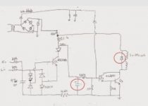
Here's my circuit
https://picasaweb.google.com/110639...authkey=Gv1sRgCPrFh7eZlY_RugE&feat=directlink
I found some help on this page, he explains the flyback diode issue.
Loudspeaker Protection and Muting
The problem now is finding out another way to do the turn-on delay, without slowing the response of the circuit. Does anyone have any suggestions? Or is there anything else I should consider?
Here's my circuit
https://picasaweb.google.com/110639...authkey=Gv1sRgCPrFh7eZlY_RugE&feat=directlink
I found some help on this page, he explains the flyback diode issue.
Loudspeaker Protection and Muting
If you rearrange the circuit like the attached, the timing cap could be much smaller and the diode would discharge the cap quickly when Q1 conducts. E
Thanks for the suggestion. I tried it but it didn't work like this. I actually needed a larger cap, and response wasn't better, maybe even worse. Could have been my implementation. Also the cap would still have to discharge through the 2.2k resistor on the bottom of the schematic.
But I did find a configuration that gave me acceptable results. I added a 10k resistor in series with the timing cap. That meant it took longer to charge, so the cap value was decreased to 22uf. The delay is much better, as the transistor can't draw base current fast enough to stay on, because the 10k resistor is in the way. (Not sure if that explanation is quite right, but the results are solid)
It took some thought to come up with a test procedure to measure the delay. I wanted to see how much actual woofer pop it created. And a DC bench supply was shown to not work the same, it had to be DC from a power amp. I took my signal generator, and hooked it to the power amp of a unit, after the input cap. Then, using the DC offset control on the signal gen, I could make the output of the power amp swing from -36V to +36V. I ran this to a test woofer, though my circuit.
Also, would the way I used the same detector stage for both channels hurt the sound at all?
Last edited:
When I put it in my external enclosure, with these updates, powered by a transformer, bridge, and smoothing cap, as shown in the schematic, it behaved differently. Before I was powering it with the DC bench supply. The turnon delay was about half the length, and I couldn't get the delay when the relay is turned off to an acceptable level. Why is it different?
Your AC detector will not work. Read the link.
http://www.diyaudio.com/forums/soli...ssing-cycle-detector-off-mute-controller.html
Gajanan Phadte
http://www.diyaudio.com/forums/soli...ssing-cycle-detector-off-mute-controller.html
Gajanan Phadte
Last edited:
I designed my own DC protect and anti power up thump circuit myself.
I used a small PIC12F508 microcontroller.
On power up it holds off the relay for four seconds.
After that if it sees one phase lasting longer than 500mS it shuts off the relay.
The program was very simple.
The circuit was pretty basic too, even had a relay on LED.
I used a small PIC12F508 microcontroller.
On power up it holds off the relay for four seconds.
After that if it sees one phase lasting longer than 500mS it shuts off the relay.
The program was very simple.
The circuit was pretty basic too, even had a relay on LED.
An externally hosted image should be here but it was not working when we last tested it.
Last edited:
Hi folks, currently creating a protection circuit for my amplifier also. I have created the circuit in LTspice below.
Under normal conditions the relay is energised thus allowing current to flow through the optocoupler and therefore allowing current to flow through the speaker. if DC is detected above 0.8volts the relay is de-energised and therefore cuts off power to the optocoupler.
Any suggestions to improve it?🙂

Your schematic cannot be seen and has no contrast. Change the colors and repost.
Gajanan Phadte
Gajanan below schematic with inverted colours. Hopefully easier for you to read.
Cheers
Dom

LTSpice is terrible for exporting an image. Ive just finished putting the circuit into EagleCAD and I've tweaked the circuit. See below;


Got it working satisfactorily. The BP cap in the input filter was too big, it was killing the response. Decreased from 47uf to 3.3uf.
I've previously tested the AC detector and it does work. I got it here, from EchoWars:
http://www.diyaudio.com/forums/solid-state/83588-sae-2400-turn-turn-off-pop-2.html#post967937
I've previously tested the AC detector and it does work. I got it here, from EchoWars:
http://www.diyaudio.com/forums/solid-state/83588-sae-2400-turn-turn-off-pop-2.html#post967937
Your ac detector circuit...You think it is working...
I have attached both for reference and these two are not the same.
Can you check what those two diodes do when series connected in reverse.
Gajanan Phadte
I have attached both for reference and these two are not the same.
Can you check what those two diodes do when series connected in reverse.
Gajanan Phadte
Attachments

Last edited:
- Status
- Not open for further replies.
- Home
- Design & Build
- Construction Tips
- Help with my protection circuit?