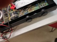
Hi , bought an A100 spares & repair from ebay. It switched on fan run and power light was on but no sound. With lid off i found R1 & R2 OC and one channel op transistors short and a dj on the volume pot. It was clear it had been worked on before as the op tranny's were MJ15003/4 types and the smoothing caps and a few other components had been changed.
I changed R1 & R2 0.47 ohm 2w and the pair of shorted transistors checked around the circuit for other obvious stuff and switched on. I now have +- 35v at R13/14 R113 / R114 on the 35v rail side. But i have anywhere between 12.5v -13v on the Zener side The voltage gradually ramps up, i switch off before letting it go any further. This is the same for all the 12 v Zener rails +ve -ve. I am not sure exactly what's going on here but would assume whatever is wrong is common to all the 12v rails? I am assuming the zener's hold the rails at bang on 12v? I have also noticed that voltages around pin 11 and 4 on IC1 also ramp and are not a the voltages suggested by the cct diagram on Mark Hennessey web site. ZD3 does not reach 5.2v either. I have checked most resistors and diodes in the power amp circuit and i also changed 12v Zener just to check. The diode that came out was fine and the new one i fitted exhibited the same fault condition. Any thoughts /help welcome. I have read the Hennessey website and most of the threads on here and find nothing relevant to this so far. Oh one more thing for interest my board is marked A100 ver5 .
For background , i was a TV & Radio service engineer back when these were new but left that side of engineering a long time ago. More than a bit rusty now in more ways than one.
So by way of a minor update. I carried on checking through the circuit and everything i tested came out ok. Apart from the ramping 12v +- rails everything else seemed ok. So i decided to give it a try. To my surprise it worked and played happily for about 15-20 mins , at which point i switched it off. I gave it about 10 mins and retried it . On switch on it immediately blew the right cahnnel. On removing the lid I was back to where i started. R1 R2 Open circuit and both right hand channel outputs short Collector -emitter. I have been back through the circuit and this time changed all the electrolytics on the right hand channel , all the 12v zenners and all 4 smoothing / PSU caps .All of the parts removed measured fine with both a meter and component tester. Leaving the outputs disconnected RHS it still ramps the 12v steadily going 12.1 through to 12.5 before i switch off. Any ideas? Is it just coincidence the same channel blew? Can anyone with this amp confirm the supply rails ? Thanks in advance , hoping someone actually replies!
Re 12V rails :- its just temperature drift , if I remember correctly zeners with a voltage below approx 6V have a negative temperature coefficient and a positive temperature coefficient above approx 6V IE around 6V is the sweet spot .
Thanks for the reply. I guess that's plausible . I think when I get it all buttoned up I will run some test leads out the side panel and see what the 12v rails do . I am guessing that if they drift much above 13v something is still wrong. I still think it odd it blew the same channel, unless the right one is more prone to going first because of the extra circuitry?
I would first check the current drawn by +/-12V rails by measuring voltage drop across R13,14 to see how close that is to the rating required to drop the raw 24V supply to approx.12. There may be a problem there or it might just be worth considering 1W rated zeners next time you shop for parts.
I think you are going to need to knock up a mains current limiting circuit using a series connected 100W incandescent mains light bulb to catch the fault as it attempts to destroy the output trannies . Also I would recommend attaching a temporary heatsink to the internal one so that you can run the amp without having the cover in place .
The diodes I'm using to replace are in4742a 1.3w . Checking the volt drop across any one of the rails I get 35v on one side and 12v going steadily upwards on the other . So assuming I'm calculating correctly 50mA at 12v falling 49, 48 47 etc. If I read the data sheet correctly they will hold 12v from 21mA ! With the op transistors removed on the faulty side the 35v rail rises to 38 v presuming cause of less load? This leads to a slightly higher current through the zeners ? Back in the day I did on occasion use a lightbulb with a mains cable for faulting but this dim bulb thing is new to me? Thanks for the input so far.
I forgot a couple of things . It's the left Chanel not the right my bad got confused. Also a good old tech friend also suggested that it might have been my speakers causing the new failure and just coincidence that it was the same channel. The speakers I'm running it on are old missions with replacement bass units , that were replaced long ago . It's possible one of them cried enough when being driven by the a100. Though doesn't explain the odd 12v rail behaviour. Would be great if someone could confirm how the 12v rail behaves ?
- Home
- Amplifiers
- Solid State
- Help with Musical Fidelity A100 12v rails issue