Not sure if this should be here on in Power Supplies, but here goes...
I am doing my best to fis up a friend's octal Aikido. The power supply needed some tlc, so I built a new one. It runs fine, but with an objectionable amount of 120Hz hum.
Put the scope on the power supply and I see a solid, waveform-perfect 2V sawtooth at the B+ point.
Here's the map - any ideas?
I am doing my best to fis up a friend's octal Aikido. The power supply needed some tlc, so I built a new one. It runs fine, but with an objectionable amount of 120Hz hum.
Put the scope on the power supply and I see a solid, waveform-perfect 2V sawtooth at the B+ point.
Here's the map - any ideas?
Attachments
Last edited:
What does the sim in PSUDII predict? If it's much less than 2V, I would strongly suspect your grounding. Can you diagram how that was done?
PSUDII predicts a 2V P-P sawtooth on the C following the choke (fancy that!)
The question is, how do I get rid of it from the Aikido's output?
Signal grounding is star at the input jacks. Power grounding is on the chassis.
The question is, how do I get rid of it from the Aikido's output?
Signal grounding is star at the input jacks. Power grounding is on the chassis.
Well, you could put a regulator after the raw supply (that's what I did for the two Aikidos I built). You can also try nulling the noise- the voltage divider values for the nulling circuit that John suggests aren't exact and the adjustment to get a decent null is pretty sharp. So you can change one of them out for a resistor that's, say, 20% smaller than nominal in series with a trimmer that's, say, 40% of nominal, then have at it.
You clearly need smoothing capacitors on both sides of the choke.
Well, something 'more' , I'd think. One choke and one cap (94uF) isn't much filtering, especially for a preamp. Even old table radios and guitar amps had more filtering than that.
Is there something special about the Aikido that lets it use noisy B+?
I'm not so professional but I suppose coaxial cable from to the ground could help you to solve the problem if it come from AC noise. anyway you'll not loose anything if you try it even it simple.
Excuse my ignorance, but what is supposed to be the purpose of the diode across the choke? This will bypass the choke on the downward swings of the AC, so destroying the whole point of a 'choke input' supply, by killing the choke current.
Is there something special about the Aikido that lets it use noisy B+?
Yes, it uses a noise-canceling tweak. That's its "claim to fame" and the origin of the "Aikido" moniker.
If you short out the choke you will get a 300V supply with similar ripple. Then RC smoothing can drop and smooth it, but it would have high DC impedance.
If you remove the extra diode you will get a 200V supply with less ripple, and probably a lower output impedance. You could boost the voltage a little by adding a small capacitor before the choke.
If you remove the extra diode you will get a 200V supply with less ripple, and probably a lower output impedance. You could boost the voltage a little by adding a small capacitor before the choke.
Yes, it uses a noise-canceling tweak. That's its "claim to fame" and the origin of the "Aikido" moniker.
Thanks, SY.
Lots to learn.......
(But I still like less ripple in the DC!)
But I still like less ripple in the DC!
So do I. Regulators are wonderful things. 😀
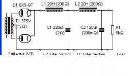
I'm still puzzled by the extra diode. Could someone tell me what they think it is supposed to do? As far as I can see, it gives the disadvantages of both a choke input and capacitor input supply at the same time. Each half cycle the choke starts from zero current, so you get a high output impedance. In what sense is this a good thing?
Excuse my ignorance, but what is supposed to be the purpose of the diode across the choke?
I was wondering about that too.😕
jeff
Somebody read about it somewhere on the Internet, so it has to be true.😀
If I were to guess (and honestly, I didn't even notice it until you pointed it out), someone saw anti-kickback diodes used somewhere and decided that this would be a dandy way to protect his circuit from the evils of kickback.
If I were to guess (and honestly, I didn't even notice it until you pointed it out), someone saw anti-kickback diodes used somewhere and decided that this would be a dandy way to protect his circuit from the evils of kickback.
You could be right! The operation of a choke input supply is a bit counter-intuitive, as it involves the current and voltage across the choke being in opposite directions for part of the cycle. Maybe someone read about the diode often needed across a relay coil and though that all inductors need one.
OK, my stab at it.....
First off, cap before the choke - 47-100uF, then choke (with/without diode, I'd say take it out to try at least), then another cap. You could also try a RC after that again.
The other thing that you haven't mentioned at all is the heaters. If you are using AC heaters without a centre tap, then do wire in a pot (270-500R) with the in and out wired to heater +/- on the PCB and with the wiper tied to 1/4 to 1/3 of the B+. Adjust the pot to get lowest hum. Made a big difference on my octal aikido, which still hums a bit btw.
A lot of this is in the aikido manuals which you can download from broskies site....
With a decent size reservoir cap before the choke it becomes a cap input PSU. Then the choke is merely a smoothing element with a voltage drop due to its resistance, so a reverse diode across it will do precisely nothing.
Could the OP tell us where he found the PSU design? That might help us discover what was in the mind of the designer.
Could the OP tell us where he found the PSU design? That might help us discover what was in the mind of the designer.
Won't 'adding' a cap before the choke mess up the OP's target B+ voltage?
Another RC section or two afterward to drop the voltage?
Another RC section or two afterward to drop the voltage?
- Status
- Not open for further replies.
- Home
- Source & Line
- Analog Line Level
- Help with Hum - Hum Help - Aikido