Dear Experts --
I'm working on a project and could really benefit from your experience. I'm technically trained, but am a first-time speaker designer. The design is a dual-ported guitar speaker cabinet, which will be loaded with a pair of 12" Celestion speakers. Note that a guitar cabinet is "part of the instrument", in conjunction with the amplifier, effects, and the guitar itself. So, a flat frequency response is not necessarily the goal -- this stands in distinction to design priorities for hi-fi speakers. I chose a ported design for a bit of a bass boost, for the look it would give to the cabinet, and for the added design challenge. I worked carefully through the description of the physics of vented speaker boxes outlined here http://personalpages.tds.net/~fdeck/bass/speaker2.pdf by a bass player & physicist named Francis Deck. I coded up my own simulations in Mathematica and have generated plots. These have been compared to WinISD and seem to agree. I'll post a view of the blueprints and several of these plots below for your inspection. I can give any number of additional details on request, including the Thiele-Small parameters and nominal design dimensions, etc. For now though, let me give just a few additional particulars, formulate my questions, and describe the places where I am becoming a bit (or very) uncertain.
Guitar speakers have a pretty limited xMax, maybe 1.2mm or so. Actually, Celestion advises against ported cabinets Guidelines for designing a guitar speaker cab , and don't generally publish their Theile-Small parameters (other manufacturers with similar "clones" do disclose their measurements and I've used this information). There are several (probably all sensible) reasons for this, including: 1) guitar speakers are highly non-linear and do not operate at "small signal", 2) they believe that material selection and sound construction techniques are more impactful than acoustic analysis, 3) there is a danger of damaging cones with large excursion below the port tuning. Having said that, there are several successful vented guitar cabinet designs, such as this Dr. Z Amplification | Z Best, this 1x12 Front Ported Thiele Guitar Amplifier Cabinet | MESA/Boogie(R), and this ported cabs (from a well-regarded custom cabinet builder).
Based on my nominal design parameters, it looks like excursion is not a major problem down to about 60 Hz. This is good news, since the low E on a Guitar in standard tuning is around 80 Hz. Even a seven string guitar with a low B goes down only to about 60 Hz. Nevertheless, it seemed like a High-Pass might be a sensible protection to guarantee that the excursion cannot damage the cone under any conceivable usage scenario (excluding extreme over-power). This is where things get very interesting (for me), and I first noticed something that I expect many of you are already very well experienced with. I looked at a stock https://www.parts-express.com/80-hz-high-pass-8-ohm-crossover--266-458 2nd-order 80 Hz HPF from Part-Express. It is built for a Butterworth characteristic ( Q=1/sqrt[2] ) at the nominal impedance ( 8 Ohm ) of my drivers ( a pair of 16 Ohm speakers in parallel ). BUT ... the impedance of the drivers is variable and NOT purely resistive. Moreover, the correct impedance to use would seem to be that of the coupled electro-mechanical driver/box/port system. The non-flat characteristic disrupts the Q factor and the reactive components screw with the tuning. Having derived the transfer function, it actually appears that the voltage amplitude at the driver terminals can in fact substantially exceed that at the amplifier terminals (this is OK in principle ... a voltage gain >1 can be physical, although a power gain could not be, but it really surprised me). This can apparently create really nasty spectral peaks, and maybe create more trouble with over-excursion than I was dealing with in the first place. Incidentally, the WinISD HPF filters behave more like I would have guessed initially, but they would seem to be "preamp" type filters, that are decoupled from the load.
My most basic questions / requests are these following. Could you please sanity-check my plots and let me know if my conclusions seem to be on track? Or, are the runaway behaviors I'm projecting with the HPF not physical? If the projections are correct, could you please help me understand how crossover designers typically deal with these sorts of problems (I've read a bit about Zobel's, impedance compensation, etc., but it seems perhaps that you favor fully customizing the x-over design to the environment ... )? Could you please make any design suggestions that seem suitable?
Before I sign off to wait on comments, let me throw one more wrench into the machinery. Guitar amplifiers (generally, traditionally) are tube amplifiers, valued for their damping, compression, and soft clipping characterstics (as well as other more subtle interactions with the cabinet). These amps have a high output impedance (let's call it 8 Ohms) and behave more like constant current (or maybe constant power?) sources than constant voltage sources (if I understand correctly). A well-known consequence is that one never powers a guitar head without a connected load ... it creates rapid collapse of the magnetic field in the output transformer, and associated extreme voltages, which can spark and damage the transformer or the tubes (the output transformer is required because tubes are low current high voltage ... thousands of volts typically). This surely affects the story as well.
Thanks very much --
Joel 😎
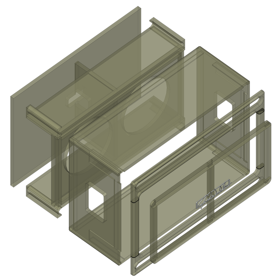
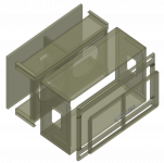
Projection of the CAD drawings for the cabinet:
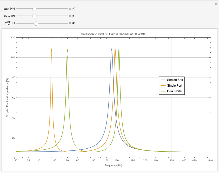
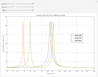
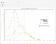
The coupled electro-mechanical impedance (ratio of complex voltage over current phasors) magnitude with a sealed box and one or two slot ports. The ports add poles (resonances) associate with the port tuning frequency.
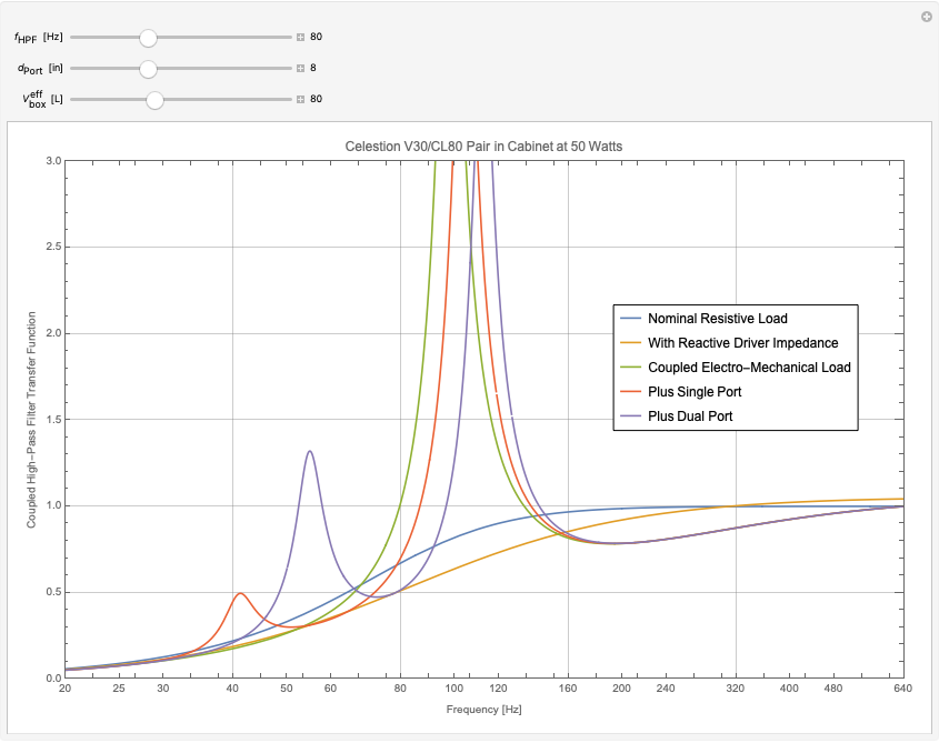
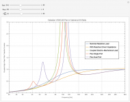
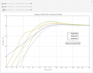
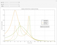
The transfer function of a (nominally Butterworth at 8 Ohms) 2nd order inductive/capacitive High Pass Filter, using 1) the nominal driver impedance, 2) the resistive / reactive components of the driver only, 3) the computed electro-mechanical impedance from the prior graph.
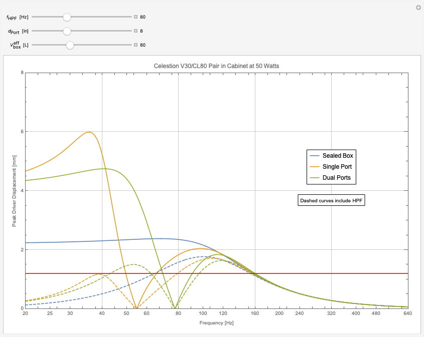
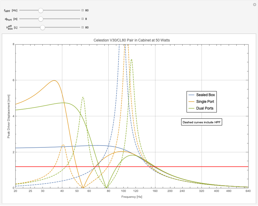
The projected cone excursion in [mm] at 50 [Watts]. Dotted curves show the effect of the HPF in the IDEALIZED (nominal impedance) scenario.
The projected cone excursion in [mm] at 50 [Watts]. Dotted curves show the effect of the HPF applying the electro-mechanical impedance from the second plot.
The projected port velocity amplitude in [Mach]. Dotted curves show the effect of the HPF in the IDEALIZED (nominal impedance) scenario.
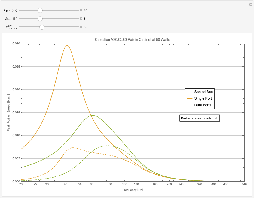
The projected port velocity amplitude in [Mach]. Dotted curves show the effect of the HPF applying the electro-mechanical impedance from the second plot.

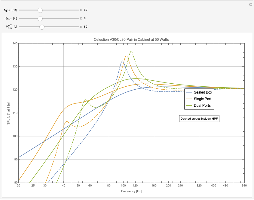
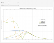
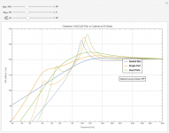
The projected SPL in dB over reference at 1 [m] with 50 [W] of Power. Dotted curves show the effect of the HPF in the IDEALIZED (nominal impedance) scenario.
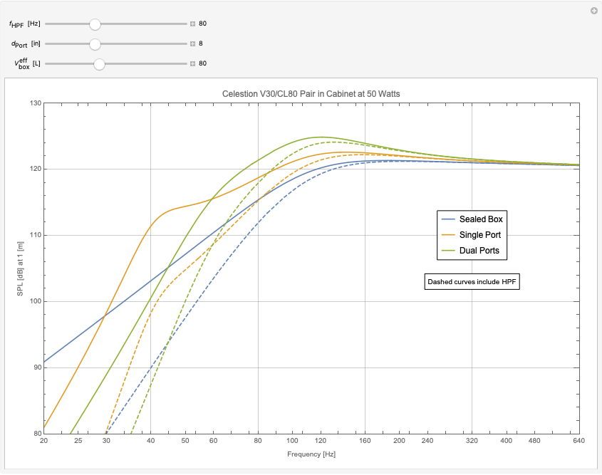
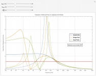
The projected SPL in dB over reference at 1 [m] with 50 [W] of Power. Dotted curves show the effect of the HPF applying the electro-mechanical impedance from the second plot.
I'm working on a project and could really benefit from your experience. I'm technically trained, but am a first-time speaker designer. The design is a dual-ported guitar speaker cabinet, which will be loaded with a pair of 12" Celestion speakers. Note that a guitar cabinet is "part of the instrument", in conjunction with the amplifier, effects, and the guitar itself. So, a flat frequency response is not necessarily the goal -- this stands in distinction to design priorities for hi-fi speakers. I chose a ported design for a bit of a bass boost, for the look it would give to the cabinet, and for the added design challenge. I worked carefully through the description of the physics of vented speaker boxes outlined here http://personalpages.tds.net/~fdeck/bass/speaker2.pdf by a bass player & physicist named Francis Deck. I coded up my own simulations in Mathematica and have generated plots. These have been compared to WinISD and seem to agree. I'll post a view of the blueprints and several of these plots below for your inspection. I can give any number of additional details on request, including the Thiele-Small parameters and nominal design dimensions, etc. For now though, let me give just a few additional particulars, formulate my questions, and describe the places where I am becoming a bit (or very) uncertain.
Guitar speakers have a pretty limited xMax, maybe 1.2mm or so. Actually, Celestion advises against ported cabinets Guidelines for designing a guitar speaker cab , and don't generally publish their Theile-Small parameters (other manufacturers with similar "clones" do disclose their measurements and I've used this information). There are several (probably all sensible) reasons for this, including: 1) guitar speakers are highly non-linear and do not operate at "small signal", 2) they believe that material selection and sound construction techniques are more impactful than acoustic analysis, 3) there is a danger of damaging cones with large excursion below the port tuning. Having said that, there are several successful vented guitar cabinet designs, such as this Dr. Z Amplification | Z Best, this 1x12 Front Ported Thiele Guitar Amplifier Cabinet | MESA/Boogie(R), and this ported cabs (from a well-regarded custom cabinet builder).
Based on my nominal design parameters, it looks like excursion is not a major problem down to about 60 Hz. This is good news, since the low E on a Guitar in standard tuning is around 80 Hz. Even a seven string guitar with a low B goes down only to about 60 Hz. Nevertheless, it seemed like a High-Pass might be a sensible protection to guarantee that the excursion cannot damage the cone under any conceivable usage scenario (excluding extreme over-power). This is where things get very interesting (for me), and I first noticed something that I expect many of you are already very well experienced with. I looked at a stock https://www.parts-express.com/80-hz-high-pass-8-ohm-crossover--266-458 2nd-order 80 Hz HPF from Part-Express. It is built for a Butterworth characteristic ( Q=1/sqrt[2] ) at the nominal impedance ( 8 Ohm ) of my drivers ( a pair of 16 Ohm speakers in parallel ). BUT ... the impedance of the drivers is variable and NOT purely resistive. Moreover, the correct impedance to use would seem to be that of the coupled electro-mechanical driver/box/port system. The non-flat characteristic disrupts the Q factor and the reactive components screw with the tuning. Having derived the transfer function, it actually appears that the voltage amplitude at the driver terminals can in fact substantially exceed that at the amplifier terminals (this is OK in principle ... a voltage gain >1 can be physical, although a power gain could not be, but it really surprised me). This can apparently create really nasty spectral peaks, and maybe create more trouble with over-excursion than I was dealing with in the first place. Incidentally, the WinISD HPF filters behave more like I would have guessed initially, but they would seem to be "preamp" type filters, that are decoupled from the load.
My most basic questions / requests are these following. Could you please sanity-check my plots and let me know if my conclusions seem to be on track? Or, are the runaway behaviors I'm projecting with the HPF not physical? If the projections are correct, could you please help me understand how crossover designers typically deal with these sorts of problems (I've read a bit about Zobel's, impedance compensation, etc., but it seems perhaps that you favor fully customizing the x-over design to the environment ... )? Could you please make any design suggestions that seem suitable?
Before I sign off to wait on comments, let me throw one more wrench into the machinery. Guitar amplifiers (generally, traditionally) are tube amplifiers, valued for their damping, compression, and soft clipping characterstics (as well as other more subtle interactions with the cabinet). These amps have a high output impedance (let's call it 8 Ohms) and behave more like constant current (or maybe constant power?) sources than constant voltage sources (if I understand correctly). A well-known consequence is that one never powers a guitar head without a connected load ... it creates rapid collapse of the magnetic field in the output transformer, and associated extreme voltages, which can spark and damage the transformer or the tubes (the output transformer is required because tubes are low current high voltage ... thousands of volts typically). This surely affects the story as well.
Thanks very much --
Joel 😎
Projection of the CAD drawings for the cabinet:
The coupled electro-mechanical impedance (ratio of complex voltage over current phasors) magnitude with a sealed box and one or two slot ports. The ports add poles (resonances) associate with the port tuning frequency.
The transfer function of a (nominally Butterworth at 8 Ohms) 2nd order inductive/capacitive High Pass Filter, using 1) the nominal driver impedance, 2) the resistive / reactive components of the driver only, 3) the computed electro-mechanical impedance from the prior graph.
The projected cone excursion in [mm] at 50 [Watts]. Dotted curves show the effect of the HPF in the IDEALIZED (nominal impedance) scenario.
The projected cone excursion in [mm] at 50 [Watts]. Dotted curves show the effect of the HPF applying the electro-mechanical impedance from the second plot.
The projected port velocity amplitude in [Mach]. Dotted curves show the effect of the HPF in the IDEALIZED (nominal impedance) scenario.
The projected port velocity amplitude in [Mach]. Dotted curves show the effect of the HPF applying the electro-mechanical impedance from the second plot.
The projected SPL in dB over reference at 1 [m] with 50 [W] of Power. Dotted curves show the effect of the HPF in the IDEALIZED (nominal impedance) scenario.
The projected SPL in dB over reference at 1 [m] with 50 [W] of Power. Dotted curves show the effect of the HPF applying the electro-mechanical impedance from the second plot.
Attachments
-
 Impedance.png61.3 KB · Views: 294
 -
 Transfer_Function.png72.8 KB · Views: 313
 -
 Excursion_ideal.png63.1 KB · Views: 278
 -
 Excursion_coupled.png86.2 KB · Views: 276
 -
 SPL_ideal.png69.4 KB · Views: 315
 -
 SPL_coupled.png71.7 KB · Views: 288
 -
 expanded.png461.2 KB · Views: 293
 -
 Air_Speed_ideal.png60.3 KB · Views: 300
 -
 Air_Speed_coupled.png73.5 KB · Views: 274
I may not be following you totally, but Im right behind you!
I built a 1x12, and tried semi open, closed and finally ported. That last step gave it the big-cab tone I was after, and I could sell my 4x12. Written up here:
Speaker cab for electric and acoustic | GuitarNutz 2
I used WinISD, using properties included for a G12M. Also the WGS site and tbe properties for their Veteran 30. My cab has a Vintage 30 in it.
My approach to the ports was to set a resonance a bit below guitar frequencies, and the tail of that lifts the lows without creating a bass boom. I have 3 rear ports. Calcs and measurements on that thread.
Other relevant info i have:
Im into designing reactive attenuators on tbe Marshall forum. One of the keys to getting those right is understanding the real output Z of the amp. Ive measured 20 ohms on my Vintage Modern and about 40 on my old dsl combo, for 8 Ohm tap. These are small signal values, but this is still important. Even distorted tones have clean parts.
Finally, there are plots of complex impedance of actual cabs online. On TGP, Mike Lind has posted a full data file of the impedance and phase of a 4x12 green back cab, showing a resonance at 120hz.
Attenuators and Load boxes | The Gear Page
- Status
- Not open for further replies.