Hello,
First I will try to describe what I have and want to achieve.
I have Renegade REN1100s 4 channel car amplifier with Toshiba A1941 & C5198 final stage, that I would like to run in 2x bridge (for dual voice coil subwoofer).
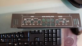
The problem is that 2channels have LPF and bass boost and others two don`t... Here is the picture of the plate:

I want to have LPF and bass boost on all channels, so I need to cut the signal lines on 2 channels that don`t have LPF and bass boost and apply the signal from two channels that have LPF and bass boost...
But I don`t know where or how to look for the right spot... I know that it`s a matter of desoldering 2 resistors or capacitors on 2 channels any "jumping" the signal from other 2 channels...
I know that I need to find the "preamp out - amp in" spot...
My idea was to touch capacitors or resistors between the preamp and amp and listen for same noises, meause voltage to make sure it`s low and apply mp3 source to confirm that I have the right spot, but pcb is a bit complicated and I have a lack of knowledge...
I can`t find schematics & pcb traces are not visible on both sides, there are no components or jumpers on bottom side of PCB...
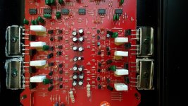
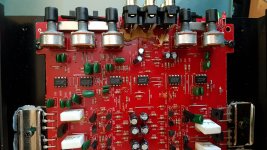
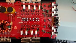
Here are the pictures of pre-amp and amp stages...


I know that someone who understand amp`s topology could lead me on the right path... I don`t have much experience with transistor amps, just IC`s, so that is my problem
First I will try to describe what I have and want to achieve.
I have Renegade REN1100s 4 channel car amplifier with Toshiba A1941 & C5198 final stage, that I would like to run in 2x bridge (for dual voice coil subwoofer).
The problem is that 2channels have LPF and bass boost and others two don`t... Here is the picture of the plate:

I want to have LPF and bass boost on all channels, so I need to cut the signal lines on 2 channels that don`t have LPF and bass boost and apply the signal from two channels that have LPF and bass boost...
But I don`t know where or how to look for the right spot... I know that it`s a matter of desoldering 2 resistors or capacitors on 2 channels any "jumping" the signal from other 2 channels...
I know that I need to find the "preamp out - amp in" spot...
My idea was to touch capacitors or resistors between the preamp and amp and listen for same noises, meause voltage to make sure it`s low and apply mp3 source to confirm that I have the right spot, but pcb is a bit complicated and I have a lack of knowledge...
I can`t find schematics & pcb traces are not visible on both sides, there are no components or jumpers on bottom side of PCB...
Here are the pictures of pre-amp and amp stages...


I know that someone who understand amp`s topology could lead me on the right path... I don`t have much experience with transistor amps, just IC`s, so that is my problem
Last edited:
What you want to do, you can, but you need to flip the board to watch the circuit board.
Then post a picture here, I can help you, but it must be in high definition.
Also, take a picture of the front plate on the side of the speaker connections.
Then post a picture here, I can help you, but it must be in high definition.
Also, take a picture of the front plate on the side of the speaker connections.
Hello, traces are not visible, should I dissasamble and take a photo anyway? I will take and post photo of front plate when I get home... thank you for help 🙂What you want to do, you can, but you need to flip the board to watch the circuit board.
Then post a picture here, I can help you, but it must be in high definition.
Also, take a picture of the front plate on the side of the speaker connections.
To upload photos click the following:
Go Advanced
Manage Attachments
Browse
Upload
Repeat as necessary
Go Advanced
Manage Attachments
Browse
Upload
Repeat as necessary
Traces are visible under the card, necessarily.Hello, traces are not visible, should I dissasamble and take a photo anyway? I will take and post photo of front plate when I get home... thank you for help 🙂
Otherwise, where do all the signals walk?
Do not worry, lift the whole board from its chassis and take a picture really in high definition.
do not forget the front panel of the connections.
I had it removed before, I installed it back after I saw traces aren't visible. Pcb is solid red.Traces are visible under the card, necessarily.
Otherwise, where do all the signals walk?
Do not worry, lift the whole board from its chassis and take a picture really in high definition.
do not forget the front panel of the connections.
hello, thats the cheapest amp you can in germany. there are a lot of traces under the board.if you are affraid, no problem. you can buy something like a rca lowpass. thats a filter, wich have to be connected between the rca cables. maybe thats the better choice for you.
hello, thats the cheapest amp you can in germany. there are a lot of traces under the board.if you are affraid, no problem. you can buy something like a rca lowpass. thats a filter, wich have to be connected between the rca cables. maybe thats the better choice for you.
Hello,
No I'm not affraid, I had the board removed already, but didn't took photo at the time. I know that there are traces, but they are invisible, whole board is solid red...
yes, i know. but the traces are a little higher than the board, so uneven. Without traces, it is not possible to now where you must bridge something.
Why not something like this with internal crossovers set to full range? Not variable, but is just an example. Assuming the head unit doesn't have the settings to achieve this.
Boss Electronic Crossover Sub Woofer input & output AVA-CR105A Subwoofer | eBay
Honestly, if it were me, I'd sell that amp and get something that fit my needs without having to add, or change anything inside / risk blowing it up. There are so many small amplifiers like this that can be had cheap, either mono or 2 channel.
At any rate, good luck with your project.
Android... has LPF at I would say about 250hz, no bass boost or any option like that... just 3band eq, fader and balance 🙁What head unit do you have?
I had pioneer in my previous car so I know what you were thinking about 😎
That could do it 😀Why not something like this with internal crossovers set to full range? Not variable, but is just an example. Assuming the head unit doesn't have the settings to achieve this.
Boss Electronic Crossover Sub Woofer input & output AVA-CR105A Subwoofer | eBay
Honestly, if it were me, I'd sell that amp and get something that fit my needs without having to add, or change anything inside / risk blowing it up. There are so many small amplifiers like this that can be had cheap, either mono or 2 channel.
At any rate, good luck with your project.
I need this just temporary, I need to buy 1000w rms amp so it won`t be cheap...
Thank you 🙂
- Status
- Not open for further replies.
- Home
- General Interest
- Car Audio
- Help with hacking this amplifier..