I would like a build a test DIY eletrostatic speaker out of intrest. What would be the best material to make the stators out of? Perforated aluminum, brass, carbon steel, galvinised, plane steel, or stainless steel. Also, can i have just one big pannel for high, mid, and low? Or should i have seperate pannels for each? How thick should the stators be? How big should the holes be? How far aprt should te holes be? Can i order it in a roll and flaten it?
http://www.mcnichols.com/products/perforated/images/roundhole/pics/sizes_p4.gif
http://www.mcnichols.com/products/perforated/images/roundhole/pics/sizes_p5.gif
http://www.mcnichols.com/products/perforated/images/roundhole/pics/sizes_p4.gif
http://www.mcnichols.com/products/perforated/images/roundhole/pics/sizes_p5.gif
In this link you have the "Spider ESL" (By Tim Weert), it is a full-range electrostat à la QUAD ESL-63, they used adapted stators in ring shapes to create higher freqs more from the middle of the membrane:
http://esl.hifi.nl/project04.htm
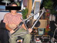
On the old photo you can see my QUAD ESL-57 mid-treble panels (I got rid of the bass panels, replaced them for a sub...) I still have 3 other panels I stripped for parts, could do some more investigating for you...
More interesting links:
http://sound.westhost.com/project105.htm
http://www.sacdmods.com/ESL/index.htm
http://amasci.com/esloud/eslhwto.html
http://esl.hifi.nl/project04.htm
On the old photo you can see my QUAD ESL-57 mid-treble panels (I got rid of the bass panels, replaced them for a sub...) I still have 3 other panels I stripped for parts, could do some more investigating for you...
More interesting links:
http://sound.westhost.com/project105.htm
http://www.sacdmods.com/ESL/index.htm
http://amasci.com/esloud/eslhwto.html
Attachments
The best material for a test speaker is whatever is readily available to you easily/cheaply. The material doesn't matter as long as it is electrically conductive, i.e. metal. You will not get better performance by buying exotic materials or by having materials plated with gold or platinum. Steel is heavier than aluminum, so you may want to go with aluminum, but it costs more.
Of course, you can make wire stators, but that's a lot of extra effort that may or may not be worth the trouble. The difference between wire and perforated stators is mainly cosmetic. Another way to go is to attach window screen to a rigid structure such as a fluorescent lamp grid. That can be a very inexpensive way to go.
You can use separate panels for different frequency ranges, but that would be ignoring one of the best characteristics of ESLs- wide bandwidth. If you are going to break up the audio band into multiple parts and use crossovers you may as well use cone type drivers and save yourself the expense and trouble of making ESLs. For a test driver I think you should start with a medium size panel and drive it full-range to see what it sounds like. Later, when you start throwing in crossovers, you'll know what you gained and what you gave up.
Unless you have a sheet metal shop, don't expect to be able to flatten rolled up sheet metal. Get your material cut to size and flattened.
Hole sizes and spacing really aren't critical, but you will get maximum efficiency from the speaker by maximizing % hole area. As a practical matter, commonly available perforated sheet with staggered hole pattern can get up to about 60% open area. Hole size between 1/8 and 1/4" (3-6mm) is fine.
If you have a source of DC bias and a transformer to step up the audio voltage, almost anything you throw together for a driver will make sound. It is hard to make an ESL that doesn't work because it is so simple.
I_F
I never heard of useing wire before as a stator. Good idea. I can see many hundreds of hours going into it.
Is there any specific way the wire should be wound into the stator or is that spider like that only for looks? Is the mylar one big piece or is it divided up for high and mid range inside the esl?
edit: The last site talks about parts that are needed. It says use a 15-20watt output transformer. Would i have to use a bigger one if i wanted to make a bigger pannel? or would a little one work fine?
Fwiw, there are several threads that are pretty recent that go through most of the issues in building an ESL... if you take the time to read them through most of your questions will be answered!
Then you can get at the details and some of the variations in methods and materials...
_-_-bear
Then you can get at the details and some of the variations in methods and materials...
_-_-bear
bear said:Fwiw, there are several threads that are pretty recent that go through most of the issues in building an ESL... if you take the time to read them through most of your questions will be answered!
Then you can get at the details and some of the variations in methods and materials...
_-_-bear
I second this advise. After building my own ESL's and then reading the ESL construction threads on this site, I was amazed at the cleaver solutions to some vexing stator construction problems. If you are serious about doing wire stators, spend some time reading the fabrication threads...Good stuff.
Inother words, there are some smart cookies here.
Sheldon
My eyes are burning from reading at the moment, i had know idea there was this much good stuff. Its all just hard to find though.
I have not found anything yet regarding my transformer question and i have not have the term "output tranformer" even used. Is there some other type that people are useing?
I have seen 32-20awg wire used, is smaller better?
I think i have decided on a 40% open stator. ya?
I think i want to use magnet wire. ya?
I have also read a few threads on voltages but i don't exactly understand. Correct me if i am wrong: The mylar is charged with 1kv-5kv. The audio is steped up to the same voltage as the stator is.
ak_47_boy said:
I have also read a few threads on voltages but i don't exactly understand. Correct me if i am wrong: The mylar is charged with 1kv-5kv. The audio is steped up to the same voltage as the stator is.
You are correct.
As for the wire, I think it won't matter much.
As for the magnet wire, I don't know, if it's conductive I guess it's okay.
As for the output transformer, I think that they mean the power it can handle from the amp. In this link http://sound.westhost.com/project1053.htm they use very common 100V speaker line transformers as step-up transformers. A relatively cheap way to go, there's also a "more power" option....
here is some additional reading material...
http://www.diyhifi.org/forums/viewtopic.php?t=305
http://www.diyhifi.org/forums/viewtopic.php?t=300
http://www.diyhifi.org/forums/viewtopic.php?t=305
http://www.diyhifi.org/forums/viewtopic.php?t=300
Sweet that will last me a day or two 🙂
I just have one more quick question that i am kind of stuck on, i am the kind of person that can't just know it works i have to know how it works. What does the audio transformer output? Does it just step up the input? What comes out each stator wire that makes the membrain move? Like change in polarity? I heard mention of AC? Is it time between pulses or what? I am confused a bit i dont understand how a transformer can do that.
I just have one more quick question that i am kind of stuck on, i am the kind of person that can't just know it works i have to know how it works. What does the audio transformer output? Does it just step up the input? What comes out each stator wire that makes the membrain move? Like change in polarity? I heard mention of AC? Is it time between pulses or what? I am confused a bit i dont understand how a transformer can do that.
Voltage is increased in the transformer, fed into the "large capacitor"(as an electrostatic panel in fact is) creates an electrostaic load (like wiping a comb on your wool sweater and being able to pick up a piece of paper).
The load should be maintained by inputting a steady 1.5 Kv or higher.
This is where the supply comes in.
The musical signal is merely "added" on top of the existing 1.5 Kv.
The allready existing load is moved back and forth causing the membrane to move accordingly....
The load should be maintained by inputting a steady 1.5 Kv or higher.
This is where the supply comes in.
The musical signal is merely "added" on top of the existing 1.5 Kv.
The allready existing load is moved back and forth causing the membrane to move accordingly....
The center tap of the audio transformer is the reference point in the speaker. Think of it as 0V. One stator will momentarily be at +1500V and the other at -1500V. The diaphragm is charged to -1500VDC. The diaphragm will be repelled by the stator at -1500V and attracted toward the +1500V side. The voltages on the stators will be constantly changing in amplitude and polarity (that's why it's called AC) and moving the diaphragm back and forth to produce sound.
The diaphragm will only move so far then stop; when the force produced by the electric field is equal and opposite the spring force due to the tension on the diaphragm. The greater the amplitude, the greater the deflection until the diaphragm can go no further and slaps against a stator.
I_F
The diaphragm will only move so far then stop; when the force produced by the electric field is equal and opposite the spring force due to the tension on the diaphragm. The greater the amplitude, the greater the deflection until the diaphragm can go no further and slaps against a stator.
I_F
How quick it slaps onto the stator depends much on the insolation material. The insulation is not only there to prevent sparkles, nylon coated stators are said to give more linear membrane movement. (progressive movent would encourage the membrane to hit the stators much quicker...).
I will search for the article I got this info from, hope I can still find it....
I will search for the article I got this info from, hope I can still find it....
Ok so when music plays the stator charge graphed would look like a sine wave. The peeks would vary depending on volume and the distance between peeks would be frequency. I think i understand good now. 🙂
I think you should look at what this guy did 😱 😱  :http://www.diyaudio.com/forums/showthread.php?s=&threadid=88236&perpage=10&pagenumber=1
:http://www.diyaudio.com/forums/showthread.php?s=&threadid=88236&perpage=10&pagenumber=1possible option....
buy yourself a used set of Acoustats and you will have everything you neet to start experimenting for very little outlay. They have wire stators so you can jump right into playing with delay lines. 0ne plus one's and model two's can be had for $300 - 500 dollars Cnd.
buy yourself a used set of Acoustats and you will have everything you neet to start experimenting for very little outlay. They have wire stators so you can jump right into playing with delay lines. 0ne plus one's and model two's can be had for $300 - 500 dollars Cnd.
They sure look good!
Here's a link of them with nice pictures:
http://www.justrealmusic.com/content/acoustat.htm
Here's a link of them with nice pictures:
http://www.justrealmusic.com/content/acoustat.htm
- Status
- Not open for further replies.
- Home
- Loudspeakers
- Planars & Exotics
- Help with DIY electrostat's