Hello everyone & I have a pair of Dahlquist DQ 10’s, been listening to them for over 40 years. I updated the crossovers and would like now to try bypassing caps C1 and C2 with Duelund cu 0.01 bypass caps. What I’m unsure of, need help with, is orientation. Here is how the caps are described:
The outer lead out, closest to the edge of the capacitor, is connected to the outer foil and as such should be connected to the lowest impedance path to ground, generally the signal output.
And, here’s the crossover schematic. If you can advise me, I’d appreciate it and thanks in advance!
The outer lead out, closest to the edge of the capacitor, is connected to the outer foil and as such should be connected to the lowest impedance path to ground, generally the signal output.
And, here’s the crossover schematic. If you can advise me, I’d appreciate it and thanks in advance!
Attachments
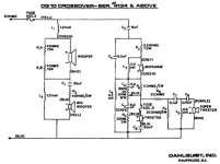
The bottom black wire is ground. So that is the side where you should connect the ground side of the capacitor.
I don't think you should bypass C1, it is for the midwoofer, which has no content that could profit from a "fast" bypass cap. Just waste of money. If it is an electrolytic cap, better use a cheap 1 micro F film foil cap to "improve" it.
From importance for sound are the larger caps that transport high frequency. C2 and C3 would be first on my list to bypass, followed by C4 and C6 (if you have more than two Duelunds).
I will not comment on the possible effect of this modification, nor the quality of overpriced boutique capacitors, as snake oil is slippery and voodoo mysterious. If you feel good with it, fine. It can not do any harm to your speaker.
Thanks for your responses. I replaced C1 with a poly film cap and it made quite a noticeable difference; it is for both the bass and mid bass. I assume the side of C1 connecting to R2 is the ground side? Bypassing all the caps might be ideal, but also a little pricy! lol By bypassing C1 and C2, as I see it, I will be affecting the entire frequency spectrum.
If you're using the right kind of 'bypass capacitor', it shouldn't matter which way around it is.
.01uF seems to me to be significantly too low in value for reasonable improvement 😕
But WOW, I've never seen the DQ-10 schematic before > How interesting !
.01uF seems to me to be significantly too low in value for reasonable improvement 😕
But WOW, I've never seen the DQ-10 schematic before > How interesting !
A loudspeaker is a very low impedance device. Any orientation will "short" hum picked up by outer foil to the ground.The outer lead out, closest to the edge of the capacitor, is connected to the outer foil and as such should be connected to the lowest impedance path to ground, generally the signal output.
This orientation may matter in a high impedance cirquit, like an amp or pre, but is of no matter in a speaker.
On the other hand, as these 0.01 mF caps are a placebo anyway, it may matter for you.
If you could hear a significant improvement with replacing C1 as you write, the old electrolytic had dried out. That is fine, measure and hear able. It was just one capacitor, but electrical compareable to 8000 Duelunds. Eight thousand. "Worth" about 720000US$. You can buy a nice boat for a small bag full of these caps. I'm sure Mr. Duelund has one...
The added Duelund will not change anything in that position, but may work for a certain type of person. Usually not for personel with an educated technical background, A-B testing, measurement and all such no nonsense, fun reducing stuff.
So ignore my fact funded, theoretical post, where to place these bypass caps, you can put them where ever you want, the effect will be the same: Great for you, none for me, best for Mr. Duelund. I could further elaborate why they don't change anything, but that probaply would only deepen your believe in alternative facts.
It is much easier to fool people than to explain to them they got fooled.
Just a hint: A perfect, highest quality, industrial made and documented 0.01 micro Farad cap is far less than 1 US$. You would not believe that 4$ of parts could make a huge difference, so someone sold them to you for 360$. Now you believe!
Have fun!
PS I never know what is more important: telling the truth and spoiling the fun or lying so as not to spoil someone's fun. Since this is just about getting money from someone for something with no real value, I was taught to be honest. Sorry.
Last edited:

The crossover network is a quite complicated serial version. Done right it saves a lot of expensive parts. Expensive in the sense of industrial production, were even a few $ count big. Integrated are components which equalize the drivers response, so it is impossible to change them for any alternative when defective.
It would be very interesting to measure the speaker after all these years.
Maybe invest 50-100$ in a calibrated measurement microfone, USB version is most simple to use with free software. That would give some insight what kind of modification could make sense for the individual speaker. Just changing working parts for other working parts will not give any improvement.
At those values, replace them entirely with Dueluend copper foil, relatively affordable: https://partsconnexion.com/duelund-0-1uf-600vdc-jdm-cu-pure-copper-foil-capacitor/
I remember eons ago seeing a test/evaluation frequency response chart and it was very very far from flat.It would be very interesting to measure the speaker after all these years.
Maybe invest 50-100$ in a calibrated measurement microfone, USB version is most simple to use with free software. That would give some insight what kind of modification could make sense for the individual speaker. Just changing working parts for other working parts will not give any improve
I also remember a subjective comment ~ "Although there seemed to be some airiness normally associated with electrostatics, there were some
strident notes apparent"
These "Strident Notes" would surely be attributed to the use of a Piezo tweeter.
Yes, MA, I’m sure you’re right about that, if you’re able to hear the Piezo. There are occasions when I’m still able and yes, it stands out.
With the help of an audio engineer, we played with the resistor values to produce a pleasing frequency curve. I’ve been listening to them since 1980 and they’ve never sounded better.
With the help of an audio engineer, we played with the resistor values to produce a pleasing frequency curve. I’ve been listening to them since 1980 and they’ve never sounded better.
MA, you asked about the drivers, who produced them:
Woofers are Advent,
The Mid woofers are Philips
The 1.5 and .75 are made by MB-Quart, a Germany company &
The super tweeter is Motorola
Woofers are Advent,
The Mid woofers are Philips
The 1.5 and .75 are made by MB-Quart, a Germany company &
The super tweeter is Motorola
- Home
- Loudspeakers
- Multi-Way
- Help with Crossover bypass caps!