
For 40 mA R1 would have to be about 15 ohms.
Chose R2 for a suitable current, depending on your supply.
You may be able to find a lower voltage than "HT".
Chose R2 for a suitable current, depending on your supply.
You may be able to find a lower voltage than "HT".
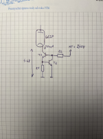
But i have only 4-6V from Cathode to GND. This is to low for LM317.Hi, here is one example.View attachment 1423673
And suitable current for T2 is? I don't know what transistors to use.For 40 mA R1 would have to be about 15 ohms.
Chose R2 for a suitable current, depending on your supply.
You may be able to find a lower voltage than "HT".
Your circuit operates above some 1 V.
Base emitter voltage of T2 is not certain and so R1 must be adjusted in accordance.
As a start chose 1 mA as operating current.
With high HT like this the power drop in R2 is very high.
Base emitter voltage of T2 is not certain and so R1 must be adjusted in accordance.
As a start chose 1 mA as operating current.
With high HT like this the power drop in R2 is very high.
I guess the first question is context, why place a CCS in the cathode unless you are making a cathode follower? As drawn this circuit would provide no more than unity gain.
The value of the current setting resistor is just Vbe of Q2 divided by your target cathode current. i.e Vbe/Icathode. Setting resistor value for collector of Q2 is more complicated as that also sets the gain of Q2. I don't recommend operating from HT if you can come up with an alternate way to bias it. Depending on transistor Hfe I would aim for Q2 collector currents that are 5 - 10% of the CCS design current. Q2 should probably be a higher Hfe type in order to optimize performance.
The value of the current setting resistor is just Vbe of Q2 divided by your target cathode current. i.e Vbe/Icathode. Setting resistor value for collector of Q2 is more complicated as that also sets the gain of Q2. I don't recommend operating from HT if you can come up with an alternate way to bias it. Depending on transistor Hfe I would aim for Q2 collector currents that are 5 - 10% of the CCS design current. Q2 should probably be a higher Hfe type in order to optimize performance.
Last edited:
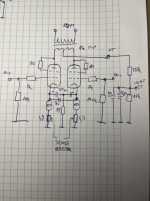
Actually it will be the output tube for a push pull spud amp. But I didn't want to draw the whole thing.Yes , sorry. Driver tube i see. I use ccs output tube cathodes sometimes.
OK I understand. For R2 i can use 220K/1W resistor. Real power drop is 0,26W. BC546C is goot choice for transistors? Or FET for the top device?Your circuit operates above some 1 V.
Base emitter voltage of T2 is not certain and so R1 must be adjusted in accordance.
As a start chose 1 mA as operating current.
With high HT like this the power drop in R2 is very high.
This is complete circuit. Is SPUD PP amp with 6E5P. Is ony class A. Why is not good choice suppllying from HT? LM317 is not good choice, cathode to ground is only 4-6V.I guess the first question is context, why place a CCS in the cathode unless you are making a cathode follower? As drawn this circuit would provide no more than unity gain.
The value of the current setting resistor is just Vbe of Q2 divided by your target cathode current. i.e Vbe/Icathode. Setting resistor value for collector of Q2 is more complicated as that also sets the gain of Q2. I don't recommend operating from HT if you can come up with an alternate way to bias it. Depending on transistor Hfe I would aim for Q2 collector currents that are 5 - 10% of the CCS design current. Q2 should probably be a higher Hfe type in order to optimize performance.
I can use CCS from this topic. But i think cascode would be better. OR?
I wanted to post this recent build by Doug De Young (the more productive half of Bug Amps). it's a gorgeous build and an elegant circuit. I can't wait to listen to it.


The amp employs a pair of 6E5P in a class A PP design with input transformers. The input txs are vintage JBLs with a number of taps that Doug has used to include switchable gain. For an amp with DC heaters, it's very quiet. The amp has respectable distortion and frequency response:


I'm sure...
The amp employs a pair of 6E5P in a class A PP design with input transformers. The input txs are vintage JBLs with a number of taps that Doug has used to include switchable gain. For an amp with DC heaters, it's very quiet. The amp has respectable distortion and frequency response:
I'm sure...
- seanzozo
- Replies: 19
- Forum: Tubes / Valves
Attachments
Last edited:
You can supply the CCS from the 10V Zener in your picture linked above.
No need to improve the simple current source beyond anything reasonable.
No need to improve the simple current source beyond anything reasonable.
The ring of two CCS is not a bad choice, you can make provisions to adjust current by adding low value pot in series with main current setting resistor. I would look at powering the 10V supply with a spare filament winding if possible. The resistive dropper from the plate supply is inefficient and if you have a component failure (zener or resistor) you could be in for a little unexpected excitement. 🙂

Look at the picture. PSU 10V and CCS. Its OK?The ring of two CCS is not a bad choice, you can make provisions to adjust current by adding low value pot in series with main current setting resistor. I would look at powering the 10V supply with a spare filament winding if possible. The resistive dropper from the plate supply is inefficient and if you have a component failure (zener or resistor) you could be in for a little unexpected excitement. 🙂
I can use one PSU for all CCS's?
What current must this PSU be able to supply?
As transistors i can use BC546C?
Attachments
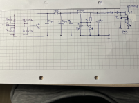
I think BC546B are a reasonable choice particularly for T2. You will be dissipating >200mW in T1 which even though well within ratings is a bit warm for TO-92 transistors IMO in a potentially warm enclosed space, at your discretion I recommend looking for a transistor for T1 only with a 1W or greater dissipation rating. (Maybe a TTC004B or similar) You also need a resistor between your 10V supply and the ccs circuitry - I'd recommend 4.7K. You show T2 as PNP which of course should be NPN.
Edit: The TTC004B is more likely to survive exposure to high voltages in the event of an internal tube short.
Edit: The TTC004B is more likely to survive exposure to high voltages in the event of an internal tube short.
Attachments
Kenvir, thank you for the practical answer. Now it's clear to me. Of course T2 is NPN, my mistake. When I use a 4K7 resistor for T2 sourcing, the current through T2 is about 2mA. I assume I should use a separate 4K7 resistor for each CCS. For the event of an internal tube short i will connect zener 35V parallel with each CCS's. I didn't draw this in the schematics. This will also protect the capacitors between the cathodes, which are rated for 35V.
- Home
- Amplifiers
- Tubes / Valves
- Help with CCS