Hello,
The amplifier in my Sony SA-CS9 home theater subwoofer is acting up and thought I would give a go at repairing it. Repairing audio amplifiers have always intrigued me and I thought now would be a good time to learn since I can't make it any worse. I do have a new digital scope as well as a DMM to help me with this and if I could get some guidance that would be awesome. I have been a lurker of this forum for sometime now and finally decided to create an account and see if I can get this amplifier going.
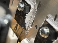
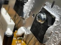
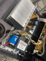
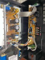
The transistors are MN2488 and MP1620. I believe this is a class A/B design amplifier because of the large power transformer? Enclosed are some pictures of the main amplifier board. The problem I'm having is no output and the power light stays red. Appearance wise I don't see anything that would suggest something is wrong. All the components look fine with no weird smells (burnt). Any guidance you can provide would be much appreciated.
The amplifier in my Sony SA-CS9 home theater subwoofer is acting up and thought I would give a go at repairing it. Repairing audio amplifiers have always intrigued me and I thought now would be a good time to learn since I can't make it any worse. I do have a new digital scope as well as a DMM to help me with this and if I could get some guidance that would be awesome. I have been a lurker of this forum for sometime now and finally decided to create an account and see if I can get this amplifier going.
The transistors are MN2488 and MP1620. I believe this is a class A/B design amplifier because of the large power transformer? Enclosed are some pictures of the main amplifier board. The problem I'm having is no output and the power light stays red. Appearance wise I don't see anything that would suggest something is wrong. All the components look fine with no weird smells (burnt). Any guidance you can provide would be much appreciated.
Attachments

Hi!
Yes, this seams to be a Class A/B amplifier unless you find other components that make it class G or H (higher efficient variations of class AB), but I doubt.
This amp uses Sanken bipolar transistors being MN2488 the NPN (positive side) and the MP1620 the PNP (negative side).
This is a 115W amplifier as I checked, so you should have only 1 x MN2488 and 1 x MP1620
Check to confirm.
For this power, you should expect power supply rails of around +33V and -33V if the woofer is 4ohm.
If it is 8ohm, you should see +47V and -47V without load. If the power is really 115W. It might be less.
So, start from the basics - check the power supply rails.
Measure the collector pin of the output transistors: positive voltage on MN2488 and negative voltage on MP1620.
Dowload the transistors datasheet so you can check the pins. They are available
If the voltages are the expected ones, you know the power supply, fuses etc are ok.
Now, check the transistors emitters since they connect to the speaker - see if there is no DC component.
Then, check the speaker with a multimeter. Disconnect from the amp, and measure its resistance - you should find something between around 3 to 8ohms depending on the speaker. This is just to see if the speaker is still good. If there is some resistance, see if the woofer is not locked.
With a 1.5V battery you can see if the woofer moves back and forth.
Then, you need to follow the signal with a scope.
Connect a signal generator 1kHz (can be your smartphone or other source) and measure the input at the printed circuit board.
Check volume knob, inversion switch if any (0 / 180deg), frequency range etc.
See if the signal reaches the first components.
To move on, you need to more or less understand this circuit to follow the signal and see where it stops.
It's a good idea to work on amp repair by connecting it through a 60W bulb in series with the mains.
Any short circuit will have limited current and you see the lamp lit.
When working with the bulb, when you power up the amp, you'll see a quick surge ligth (power supply inrush) on the bulb and then it will no longer be lit.
Keep posting here - maybe someone has the schematics.
With the schematics is very simple to find the problem.
Thank you, Ron for the detailed response. It is much appreciated!
Correct. There are only 1 x MN2488 and 1 x MP1620. The woofer has a DC resistance of 6 ohms when using my DMM. Do you think this amplifier makes its rated power of 115w with a 6 ohm woofer? The data sheets that I found for the transistors didn't mention what ohm they measured rated power at and I was curious if this is another inflated amplifier rating or if it might actually meet its spec. Normally I can check "average power" by using one of my 4 or 8 ohm braking resistors with my signal generator and scope until I see clipping, but I don't have a 6 ohm braking resistor to perform this test.
I will start with the basics as you suggested and report back. Like you I couldn't find a schematic for this amplifier but maybe someone here has one?
Thanks again.
6 ohm driver resistance is an 8 ohm speaker. The other 2 ohms are the inductance of the coils.
The common between the two 63 volt capacitors is where you put the alligator clip lead to connect the black probe of the meter. I usually use speaker return, but with an internal speaker no telling which lead is sound and which lead is return.
The transistor datasheets can be downloaded from datasheetcatalog.com
Do not use 2 hands probing the circuit. >24 volts across your heart from hand to hand can stop it. Wear no metal on hands, wrist, or neck. lower voltage at high amps can burn your flesh to charcoal. Wear safety glasses, parts can explode.
Before you power up, check from base of output transistors to collector and emitter. 0.6 v forwards, ---- or 9999 backwards. Use diode scale PNP has a negative base, NPN has a positive base. If same resistance both directions, the output transistors are damaged.
Before you power up, check fuse or circuit breaker.
You do not need a signal generator to produce 1000 hz. I use a transistor radio turned down to about 1/3 volume . If high voltage from shorted parts goes out the input, it blows up a $10 transistor radio instead of a $600 cell phone. Make sure the radio is on a station with earphones before plugging up to input.
Most AB schematics are pretty similar. Determine if the input goes to a 3 legged input transistor, or to an 8 legged IC. It will be blocked by a capacitor, which you have to find with diode scale of the meter.
Last edited:
Hi!,
Yes, the datasheet of this amp just mentions 115W. Since it's an active subwoofer, I think they though it was not important to mention the impedance.
So, being 6 ohm, you should expect supply rails around +/- 42V at collector pins of transistors without load (assuming 10% drop on load).
This is just an approximation values to start the troubleshooting.
P = Vrms^2/R
Vrms = Sqrt(R*P) = 26Vrms or 37Vpeak (top of the sine wave)
Good luck!