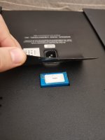
Hello everyone Please help me to switch the voltage of ml 360s to 230-240v. Who does not find it difficult to find a pad behind the sticker, pull it out and ring the short-circuited jumpers. Please help, I'm afraid to make a mistake with the voltage transfer myself.
Just write down which pins you have closed with each other
 .
.
Just write down which pins you have closed with each other
According to the manual, changing the voltage cannot be done by the user, whatever this means.
Maybe it needs a change of tranformer, but also the mains frequency can be the cause since this frequency is measured in some ML’s, requiring a firmware update or a simple external 60Hz generator to fool the system.
Hans
Maybe it needs a change of tranformer, but also the mains frequency can be the cause since this frequency is measured in some ML’s, requiring a firmware update or a simple external 60Hz generator to fool the system.
Hans
Good afternoon, Hans!According to the manual, changing the voltage cannot be done by the user, whatever this means.
Maybe it needs a change of tranformer, but also the mains frequency can be the cause since this frequency is measured in some ML’s, requiring a firmware update or a simple external 60Hz generator to fool the system.
Hans
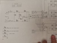
The tension changes in chips, that's for sure. This chip has its own closed jumpers. There is no blocking of the network frequency in the 360s.
Transformers are multi-voltage.
And it is possible to switch 100v 110v 115v 120v 200v 220v 230v 240v.
Attachments
I just need a 360s 230v or 240v owner.
So that he pulled out the pad and checked the closed jumpers. A matter of 5 minutes 🙂
So that he pulled out the pad and checked the closed jumpers. A matter of 5 minutes 🙂
Attachments


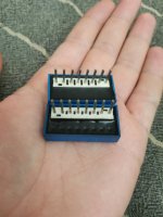
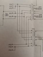
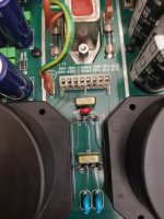
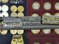
Hans, do you have any friends who have 360 or 360s? Ask to ring the jumpers. Inside they look like this:Looking at the circuit diagram that you supplied, unfortunetly doesn’t disclose a thing .
Hans
Attachments
It seems you have one block for 100V and one for 200V, true?
Which pins are connected in the two versions, maybe this will reveal some logic.
Hans
Which pins are connected in the two versions, maybe this will reveal some logic.
Hans
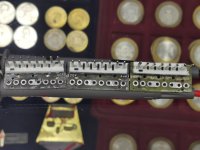
No sorry, I don’t have friends with a 360.Hans, do you have any friends who have 360 or 360s? Ask to ring the jumpers. Inside they look like this:
In the version you show 3-4 and 6-7 are connected. Is this for the 100V version ?
Hans
Yes, Hans, 3-4 and 6-7 are 100v.No sorry, I don’t have friends with a 360.
In the version you show 3-4 and 6-7 are connected. Is this for the 100V version ?
Hans
200v only 1-2 are shorted.
By calculating the voltage drop, I set it to 1-2 and 4-5, but I think it's 215V 😐 tk transformers are heated to 50-55 degrees. Tk I have a voltage of 230v + so I want to switch to 230-240v.
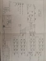
There are two transformers T1 and T30 that are 100% in parallel independent of the 8 pin plug.
So, we can concentrate on T1.
With 3-4 and 6-7 you have the two windings in T1 in parallel suited for 100 Volt.
Connecting 2-3 and 5-6 will then be suited for 120Volt.
Connecting the windings in series will change to 220V -240V, so just 4-7 for 220V and 1-2 for 240 Volt.
Hans
So, we can concentrate on T1.
With 3-4 and 6-7 you have the two windings in T1 in parallel suited for 100 Volt.
Connecting 2-3 and 5-6 will then be suited for 120Volt.
Connecting the windings in series will change to 220V -240V, so just 4-7 for 220V and 1-2 for 240 Volt.
Hans

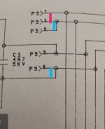
Hans, I was wrong. Here I marked the short-circuited jumpers with blue at 100v.There are two transformers T1 and T30 that are 100% in parallel independent of the 8 pin plug.
So, we can concentrate on T1.
With 3-4 and 6-7 you have the two windings in T1 in parallel suited for 100 Volt.
Connecting 2-3 and 5-6 will then be suited for 120Volt.
Connecting the windings in series will change to 220V -240V, so just 4-7 for 220V and 1-2 for 240 Volt.
Hans
Pink at 200v.
И черным пометил маркером на 100в прямо на колодке.
Attachments
To be sure what's 200 V and 240 V you could connect resp. 1-2 and 4-7 and measure with your multimeter which of the two has the higher impedance, between 3 and 6. That will be the 240Volt,
Hans
Hans
Sorry, but I don't understand pin 1/5 to pin 7, that doesn't seem to make sense.Hans, I was wrong. Here I marked the short-circuited jumpers with blue at 100v.
Pink at 200v.
И черным пометил маркером на 100в прямо на колодке.
Looking at posting #6 I see a connection between 3-4 and 6-7 for the 100V version
Hans
O.K, I see what I did wrong, counting from 1-8 instead of 8-1.
Now it makes full sense that 5-6 and 2-3 are connected for 100 Volt.
I'm also sure now that 4-7 is for 220 /240 Volt and 1-2 for 200/220Volt.
Hans
Now it makes full sense that 5-6 and 2-3 are connected for 100 Volt.
I'm also sure now that 4-7 is for 220 /240 Volt and 1-2 for 200/220Volt.
Hans

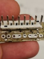
You should measure between 3 and 6 wile 4 and 7 are connected.Hans I got the wrong direction, sorry) you're right.please see if I am measuring the resistance correctly in the photo?
Between 4 and 7 is the highest resistance.
Then you will see a higher resistance between 3 and 6 as with 1 and 2 connected.
But be confident that 4-7 is the correct connection for you.
Hans
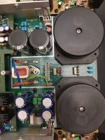
Hans, here's a photo. Did I measure it correctly? Yes, you are right, the resistance increased by 4-7 with 3-6 closed and amounted to 198 kohm.You should measure between 3 and 6 wile 4 and 7 are connected.
Then you will see a higher resistance between 3 and 6 as with 1 and 2 connected.
But be confident that 4-7 is the correct connection for you.
Hans
The resistance is between 3 - 6 98ohm with closed 4-7.
Hans, did I understand correctly that I need two jumpers to put on 3-6 and 4-7 and I will have 240v? And how do I do it on 230v?
Attachments
Last edited:
3 and 6 are the points where mains enters the 360.Hans, here's a photo. Did I measure it correctly? Yes, you are right, the resistance increased by 4-7 with 3-6 closed and amounted to 198 kohm.
The resistance is between 3 - 6 98ohm with closed 4-7.
Hans, did I understand correctly that I need two jumpers to put on 3-6 and 4-7 and I will have 240v? And how do I do it on 230v?
All you have to do is to only connect 4 to 7, that’s it and it will go for 220 for 240 Volt, so with 230 Volt you are fine.
Hans
Good afternoon, Hans! Yesterday I was afraid to put a jumper in 4-7 🙂3 and 6 are the points where mains enters the 360.
All you have to do is to only connect 4 to 7, that’s it and it will go for 220 for 240 Volt, so with 230 Volt you are fine.
Hans
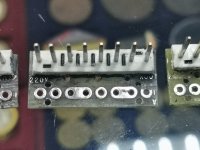
Because I don't understand how the board track could pass from 4 to 7, because on the way 5 and 6 ...
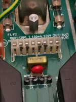
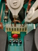
I decided to carefully open the body of the 200v jumper. And I saw that on each side of the board there are numbers with voltage. I think this is a universal power supply board and the voltage will depend on which side to solder the jumpers. Look at the photo.
There are numbers 100v 120v 220v and 240v on the board.
Is it possible that you made a mistake with 4 and 7?
Attachments
- Home
- Source & Line
- Digital Source
- Help to transfer the voltage ml 360s