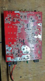
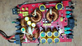
What's up friends? this time i am trying to repair and understand how this amp works. He is a Dx1000.1 kicker. My problem is in PS and in the output stage, to begin with I don't know what waves I should see in the PS stage, I understand that the uc3843b is the one that handles the PS pulses, but I don't see anything, just some very scattered peaks and I only have 1 mosfet of this stage in good condition, can it be tested with only 1 mosfet? Are there replacements for these? as they are expensive. What happens if I put them on and they burn again? What signals should I observe in the uc3843b?... Greetings
Attachments
hello! I have managed to turn on PS, and I got some irs20957s for the output of another amplifier, my question is what voltages should I have on the pads of u14 and u15 since I see some differences in the voltages and I do not want to damage the ic since I can not find new, if someone could help me I would appreciate it.
Post the voltages you have. Copy and paste the following list and fill in the blanks. Since the forum now deletes blank spaces, you'll need to add one between the colon and the numbers you enter.
Pin 1:
Pin 2:
Pin 3:
Pin 4:
Pin 5:
Pin 6:
Pin 7:
Pin 8:
Pin 9:
Pin 10:
Pin 11:
Pin 12:
Pin 13:
Pin 14:
Pin 15:
Pin 16:
Pin 1:
Pin 2:
Pin 3:
Pin 4:
Pin 5:
Pin 6:
Pin 7:
Pin 8:
Pin 9:
Pin 10:
Pin 11:
Pin 12:
Pin 13:
Pin 14:
Pin 15:
Pin 16:
without the irs20957s
IC15
Pin 1: 12.71v
Pin 2: 7.7v and gradually decreases until it reaches 0v
Pin 3: 0.293v
Pin 4: 0v
Pin 5: 0v
Pin 6: 3.3v
Pin 7: 3.3v
Pin 8: 12.7v
Pin 9: 3.3v
Pin 10: 3.3v
Pin 11: 12.7
Pin 12: 0v
Pin 13: 4.9v
Pin 14: 4.9v
Pin 15: 69v
Pin 16: 4.9v
IC14
Pin 1: 12.71v
Pin 2: 7.7v and gradually decreases until it reaches 0v
Pin 3: 0.293v
Pin 4: 0v
Pin 5: 0v
Pin 6: 0v
Pin 7: 0v
Pin 8: 12.7v
Pin 9: 0v
Pin 10: 4v
Pin 11: 12.7
Pin 12: 0v
Pin 13: 4.9v
Pin 14: 4.9v
Pin 15: 69v
Pin 16: 4.9v
Confirm that IC14 pin 9 reads 0 ohms to ground. 3.3v may have not been accurate.
Bear in mind that I don't have a Kicker diagram. I'm working from bits and pieces of other diagrams.
ZD6 is a 13v Zener.
For D106 and D206, the notes I have say 4148. LL4148?
Bear in mind that I don't have a Kicker diagram. I'm working from bits and pieces of other diagrams.
ZD6 is a 13v Zener.
For D106 and D206, the notes I have say 4148. LL4148?
I see inconsistencies between the two lists of voltages that I wouldn't expect but nothing that looks like it could damage an IC. That said, I'd like someone with more experience with these ICs to confirm this.
- Home
- General Interest
- Car Audio
- help to fix kicker dx1000.1