Hi, sorry in advance for such a dumb request, I'm almost embarassed...
I took apart a BX-9 but forgot to take a picture of how the connectors of the On/off switch go. Is anyone able to help me?
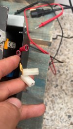
When taking it apart I stickytaped the two reds together, which makes me think they go in the top left and right, and the white ones which have a bigger connector would go in the bottom as they are further apart.
The two reds measure 45VAC between them, between white and red it measures 22.5VAC.
The reds are also connected to ground.
I'm guessing this is how they should be connected since otherwise i would be shorting the two red wires.
Can anyone confirm just for peace of mind so i dont make it smoke up the room? Thanks a lot!!
I took apart a BX-9 but forgot to take a picture of how the connectors of the On/off switch go. Is anyone able to help me?
When taking it apart I stickytaped the two reds together, which makes me think they go in the top left and right, and the white ones which have a bigger connector would go in the bottom as they are further apart.
The two reds measure 45VAC between them, between white and red it measures 22.5VAC.
The reds are also connected to ground.
I'm guessing this is how they should be connected since otherwise i would be shorting the two red wires.
Can anyone confirm just for peace of mind so i dont make it smoke up the room? Thanks a lot!!