Hello!
I'm brazilian and firstly please sorry for my english.
I came to tell my sad story hahaha
My son spitted juice on my receiver. At the same time I shut off the equipment.
After the clean there is not powering on. Going on protection mode but show the info percent from DC protection.
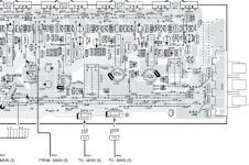
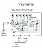
Ok. Looked at superficially I found some resistors opened. Removed and soldered the new but at the moment in connect the cables, I've inverted some connections (images 1 and 2) and since then the receiver not display anything (only horizontal lines for 0.2~0.5sec).
I hear the relay arming and desarming rapidly.
I have tested the voltages in all power supply parts and they are ok
However, I identified some voltage in PRV. Can be it. I'm going continue studying the circuit for kill this problem.
Can anyone help me in this problem?
Thank you in advance for your support.
I'm brazilian and firstly please sorry for my english.
I came to tell my sad story hahaha
My son spitted juice on my receiver. At the same time I shut off the equipment.
After the clean there is not powering on. Going on protection mode but show the info percent from DC protection.
Ok. Looked at superficially I found some resistors opened. Removed and soldered the new but at the moment in connect the cables, I've inverted some connections (images 1 and 2) and since then the receiver not display anything (only horizontal lines for 0.2~0.5sec).
I hear the relay arming and desarming rapidly.
I have tested the voltages in all power supply parts and they are ok
However, I identified some voltage in PRV. Can be it. I'm going continue studying the circuit for kill this problem.
Can anyone help me in this problem?
Thank you in advance for your support.
Attachments
Update
I have analised the pins from IC501 and found the next values:
Pin 12 - RESET - 4.8V (OK);
Pin 16 - VCC - 4.8V (OK);
Pin 20 - PDT (Power down detect input) - 4.8V (4.0V is the correct);
Pin 40 - PRI (Over current protection detect input) - 0V (OK);
Pin 46 - PRY (Power relay output) - 4.8V (OK);
Pin 63 - VCC - 4.8V (on manual the right is -29,3V, but the why I not understand);
Pin 90 - LIMDT (Limitter DC detect input) - 0.6V (0.2V is the correct);
Pin 91 - PRV (PS protection) - 3.0V (1.5V is the correct);
Pin 92 - PRD (DC protection) - 0.9V (0.3V is the correct).
Anyone have any idea what to look or change?
Hi,
If you check the micro pin voltage for 91 & 92 need to be 1 or 4+ volt. But before do anything else try to do a hard reset by grounding pin 12. Just power ON and wait few seconds and momentary ground pin 12. If everything it is OKAY it should bring the power ON. Looked like you have speaker output voltage. That it is why pin PRV and PRI are wrong. Follow the micro pin table output both should be 1. Now I do not if that it is when everything it is running good it is a fault. Need to verify what the table pin output 1 or 0 means.
If you check the micro pin voltage for 91 & 92 need to be 1 or 4+ volt. But before do anything else try to do a hard reset by grounding pin 12. Just power ON and wait few seconds and momentary ground pin 12. If everything it is OKAY it should bring the power ON. Looked like you have speaker output voltage. That it is why pin PRV and PRI are wrong. Follow the micro pin table output both should be 1. Now I do not if that it is when everything it is running good it is a fault. Need to verify what the table pin output 1 or 0 means.
Hi,
If you check the micro pin voltage for 91 & 92 need to be 1 or 4+ volt. But before do anything else try to do a hard reset by grounding pin 12. Just power ON and wait few seconds and momentary ground pin 12. If everything it is OKAY it should bring the power ON. Looked like you have speaker output voltage. That it is why pin PRV and PRI are wrong. Follow the micro pin table output both should be 1. Now I do not if that it is when everything it is running good it is a fault. Need to verify what the table pin output 1 or 0 means.
Thanks. I'll go verify.
Update:
I was able to connect and keep the equipment on, disconnecting the flat going to the voltage regulators.
I believe that the reversal of the cable I made may have damaged the central IC. The voltage outputs for image generation on the display do not provide more than 1.5V even when the equipment is turned on.
I'm giving up on getting it back.
- Status
- Not open for further replies.