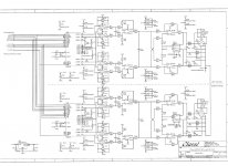
Hey guys, I have a nice sounding balanced input discrete Transimpedance I/V -output amp and I would like to slot it in before all the opamps in this circuit, is it possible to parallel up the dual dif outputs to give me balanced outputs?
I-out positives together and I-out negatives together or another way?
Cheers George
I-out positives together and I-out negatives together or another way?
Cheers George
Attachments
Last edited:
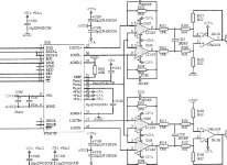
I understand from the other place I can just parrallel the I-outL+ & I-outR+ and then I-outL- & I-outR- then this gives me balanced output instead of dual dif.
But what happens to Vcom2 that goes to Pin3 of all the LT1357's
(below is a single channel magnification) if you need to press the X in the bottom left of the first attachment and this to expand it more.
Cheers George
But what happens to Vcom2 that goes to Pin3 of all the LT1357's
(below is a single channel magnification) if you need to press the X in the bottom left of the first attachment and this to expand it more.
Cheers George
Attachments
Hey guys, I have a nice sounding balanced input discrete Transimpedance I/V -output amp and I would like to slot it in before all the opamps in this circuit, is it possible to parallel up the dual dif outputs to give me balanced outputs?
I-out positives together and I-out negatives together or another way?
Cheers George
Hi George,
I'm doing something similar to what you describe in my diy dac. Basically I am running a pair of PCM1794A in mono mode, and summing the output currents prior to the differential transimpedance amplifier I am using. Note in the case of the 179x family when you run in mono mode the polarities of one of the differential output pairs is swapped depending on what channel you have selected to output - in my case I just cross connect them to maintain the proper polarity. Since the transimpedance amplifier has close to 0 input impedance there is no interaction between the dacs and the currents just sum as you would expect. Sounds great and is very simple compared to some of the hare-brained schemes I have seen.
I understand from the other place I can just parrallel the I-outL+ & I-outR+ and then I-outL- & I-outR- then this gives me balanced output instead of dual dif.
But what happens to Vcom2 that goes to Pin3 of all the LT1357's
(below is a single channel magnification) if you need to press the X in the bottom left of the first attachment and this to expand it more.
Cheers George
Hi George,
I believe Vcom2 is just a buffered dc voltage which is probably about 1/2 the reference output voltage (1/2 FS) that is fed to the I/V converter in order to allow for the cancelation of the dc offset present in the output of this converter. Depending on the common mode range of your transimpedance amplifier you might be able to ignore it, otherwise you will need to account for the offset at the input.
Edit: This is a unipolar dac which means signal baseline is about half of the analog supply voltage and applying 1/2 the reference voltage to the reference junction (+) of the I/V converter makes the dc component of the dac output common mode, the input cmrr then cancels the dc component leaving only the ac signal. If your transimpedance amplifier is truly differential and has a sufficient input CMR it should reject the dc component and you can probably safely ignore the Vcom2.
Last edited:
Thanks Kevin, maybe Vom 2 can go to input ground without link 4 being bridged, can that be done?
Here is my Transimpedance board with filter dc servo and class a single ended output, you may reconize it.
Cheers George
Hi George,
I don't believe that Vcom2 should be tied to anything in this case, tying it to ground will short it out. (You might even destroy the dac ic as these pins are not usually short circuit protected.)
FWIW I think this design was intended to accomodate a large variety of dac ICs and has sufficient input cmr to work ok with the offset.
Sorry Kevin have a close look at the diagram of the Transimpedance amp it's not really ground if you don't link no. 4.
Cheers George
Cheers George
Sorry Kevin have a close look at the diagram of the Transimpedance amp it's not really ground if you don't link no. 4.
Cheers George
Actually as long as you don't link connection 4 you do want to connect Vcom2 there - this provides the common mode reference to the input stage and based on what I see should properly compensate for the common mode dc on the input diff pair.
The numbers are bit hard to read is all.
The numbers are bit hard to read is all.
Click on the attachment (bigger) then click on the X in the bottom left (much bigger)
So this looks the goods for the vcom2 connection.
So I parallel the 2 - outputs and the 2 +outputs this then gives me -&+ balanced outputs at double the current?
I may have a problem as the data of the PCM1738 says it has 2.45mA output current, paralleled gives almost 5mA?
My Transimpedance board with 4 x PCM56 outputs (4mA per channel) from my Wadia dac just clipped at 0dbF sinewave from my test discs. I managed to drop this to just below clipping at 0dbF with a 100ohm series resistance on the input of the Transimpedance board.
But with the 5mA of the doubled PCM1738's this will need even more attenuation I think, I think I'm in trouble.
Cheers George
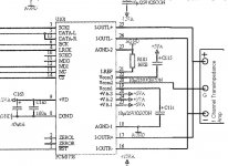
kevinkr, I'm going to try it next week, just making sure with you before I do with the attached diagram one channel only shown. (don't want to blow anything)
1: 2 x positive outputs of dac together go to + input of I/V
2: 2 x negative outputs of dac together go to - input of I/V
3 : vcom2 from dac goes to G of I/V link 4 NOT bridged.
Cheers George
1: 2 x positive outputs of dac together go to + input of I/V
2: 2 x negative outputs of dac together go to - input of I/V
3 : vcom2 from dac goes to G of I/V link 4 NOT bridged.
Cheers George
Attachments
kevinkr, I'm going to try it next week, just making sure with you before I do with the attached diagram one channel only shown. (don't want to blow anything)
1: 2 x positive outputs of dac together go to + input of I/V
2: 2 x negative outputs of dac together go to - input of I/V
3 : vcom2 from dac goes to G of I/V link 4 NOT bridged.
Cheers George
Hi George,
I think what you propose is correct, but I would take a look at the datasheet for the PCM1738. The current does sum as you have indicated and if the transimpedance amplifier cannot handle 5mA FS then you do have a problem.
One of the things I am wondering is just how close to a virtual earth the transimpedance amplifier inputs are? If they really are that good you can offset the dac current with an opposing current of 1/2 the magnitude of the FS output current making the D/A appear as a bipolar dac to the transimpedance amplifier. In this scenario you would not connect Vcom2 to the transimpedance amplifier and the output would inherently have close to 0 dc in the output at the mid point. (0 signal) Note that there is some risk of damaging the dacs if the current outputs are forced below ground and internal substrate diodes are turned on. You have to assure that the supplies feeding the transimpedance are always up first.
There may be modifications to the transimpedance amplifier that will allow it to operate at higher currents, but I am not sure about that.
An alternative would be the THS4130 which I am running at much higher currents than this - FS with the PCM1794A is about 16mA (IIRC) in mono mode in my set up.
As always caveat emptor. Be really careful as you go - I'd hate for you to roach your dac. In my case it just costs me money as the parts are all current, in your case it could be a headache.
Incidentally the changes you propose are completely worthwhile regardless of the risk. There are a lot of op-amps in the signal path, and IMHO a more theoretically perfect amplifier device there isn't - but in practice a couple of them in cascade are often (if not always) worse sounding than a few very parametrically inferior discrete devices in a much simpler circuit.. (Just my opinion... 😛 )
Last edited:
Thanks Kevin, I will do it once I have time away from the Lightspeed Attenuator orders.
LC audio say the Transimpedance amp is a just a couple of ohms input impedance when used in current mode.
I think if I increase the 16kohm I-ref resistor that goes to ground on pin 21 of the PCM1738 to say 20kohm or so, I can reduce the current output of the dac, this may well see the Transimpedance amp just under clipping at 0dbF then.
Cheers george
Thanks Kevin, I will do it once I have time away from the Lightspeed Attenuator orders.
LC audio say the Transimpedance amp is a just a couple of ohms input impedance when used in current mode.
I think if I increase the 16kohm I-ref resistor that goes to ground on pin 21 of the PCM1738 to say 20kohm or so, I can reduce the current output of the dac, this may well see the Transimpedance amp just under clipping at 0dbF then.
Cheers george
Hi George,
I think that should work just fine. This is commonly done with the PCM1794 as well. Note that you should not reduce this more than necessary to eliminate clipping at FS because it does have an implication on dynamic range and the lower current per bit moves you closer to the dac chip & transimpedance amplifier noise floors. This is probably not an issue here as most dacs have significantly more dynamic range than most systems can reproduce, and you are only trading off a few dB..
- Status
- Not open for further replies.
- Home
- Source & Line
- Digital Source
- Help on reconfiguring PCM1738 dual dif outputs please