Hello,
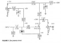
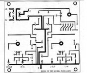
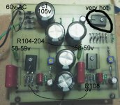
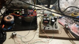
I am trying to build Mr. Pass BoZ preamp. I am following his article (https://www.passdiy.com/pdf/brideofzen.pdf). I am using the exact layout in the article. I am attaching the circuit for the preamp and the power supply and some pictures so you guys can spot my mistakes .
I made my own pcb (for the first time!) and of course have some issues 🙂
1- First problem. Mr. Pass uses a 30 0 30 transformer. I am using a single 60v. I am getting 105v across C1 (the cap is rated at 100v! and according to the article, I should get around 85v). I still get around 59v from the power supply though.
2- Maybe related to 1, the TIP29C gets really really hot. The heatsink is so small 🙂 ... what should I do?
3- I am getting slightly smaller values than what the article suggests. At the gate of the IRF610s, I have 7v (not 7.5) and have 3v Gate to Source (not 3.5v) and I have 3v at R108/R208 (not the recommended 4v). The trimmers are rotated all the way counter clock wise. Is this OK?
4- According the component placement in the article, the only way I could follow the pin out of the 3 transistors is to have them face down. Am I doing it wrong?
Any comment, advice is very much appreciated.
thank you
KJ
Attachments
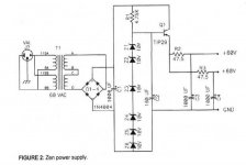

1- First problem. Mr. Pass uses a 30 0 30 transformer. I am using a single 60v. I am getting 105v across C1 (the cap is rated at 100v!
and according to the article, I should get around 85v). I still get around 59v from the power supply though.
2- Maybe related to 1, the TIP29C gets really really hot.
It might be best to get a different, smaller transformer, otherwise you'll have to do things like shunt the pass device with a power resistor.
You could use a 12V filament transformer to buck the input voltage, to decrease the output voltage by about 10%.
Or, a small Variac on the transformer primary would work well.
hmm. I was under the impression that 30 0 30 in series would give you 60v (my transform output). Ideally, I would like to use the one I have because it also powers the small dac that I will put with the preamp in the same enclosure. (it has other secondaries I use for the dac)
hmm. I was under the impression that 30 0 30 in series would give you 60v (my transform output).
Ideally, I would like to use the one I have because it also powers the small dac that I will put with the preamp in the same enclosure.
(it has other secondaries I use for the dac)
Your transformer probably can supply more current than the original transformer, so the output voltage rises when lightly loaded.
If you get a small 12V filament transformer, hook the secondary in series with your primary. When in the right polarity,
it will reduce the voltages by about 10%. If you get a 25V flament transformer, that would reduce the voltages by about 20%.
A CRC filter after the recifier instead of just the C (with enough R, of adequate W) might also do the trick.
Hello,
I am trying to build Mr. Pass BoZ preamp. I am following his article (https://www.passdiy.com/pdf/brideofzen.pdf). I am using the exact layout in the article. I am attaching the circuit for the preamp and the power supply and some pictures so you guys can spot my mistakes .
I made my own pcb (for the first time!) and of course have some issues 🙂
1- First problem. Mr. Pass uses a 30 0 30 transformer. I am using a single 60v. I am getting 105v across C1 (the cap is rated at 100v! and according to the article, I should get around 85v). I still get around 59v from the power supply though.
2- Maybe related to 1, the TIP29C gets really really hot. The heatsink is so small 🙂 ... what should I do?
3- I am getting slightly smaller values than what the article suggests. At the gate of the IRF610s, I have 7v (not 7.5) and have 3v Gate to Source (not 3.5v) and I have 3v at R108/R208 (not the recommended 4v). The trimmers are rotated all the way counter clock wise. Is this OK?
4- According the component placement in the article, the only way I could follow the pin out of the 3 transistors is to have them face down. Am I doing it wrong?
Any comment, advice is very much appreciated.
thank you
KJ
1. either use smaller xformer , or put 24V/3W bulb in series in secondary or 240R/5W resistor
2.don't use force - take a bigger hammer 😉
put bigger heatsink
3. decrease R101 to 27K and see can you get what's needed ; chase 4V at R108 , that's sole important value - other values are just for checking
4.that I can't help - lazy & don't have experience with particular pcb ; edit: that's really irrelevant - be lucid with physical arrangement , keeping electric connections ; orient heatsinks vertically , increase them etc.
Last edited:
Thanks ZM. Will follow your wise advice. You already got me out of trouble with my F5 build, so thank you again 🙂
I've got a working BOZ in my garage boxed, ready to ship, if you want it for a small fee. I'll donate the funds, minus paypal fees and shipping, to diyaudio.com. Anyone interested, PM me if interested. Tell your friends! Tell your family! 😀
Zen Mod saved the day again 🙂
I did what you said, put a 2 x 100r 3w (all I had at home) in series with transformer secondary and it took care of the extra voltage. I need to buy a more heat capable resistor, but I now know it works fine. The TIP29C is not even warm now. But I will replace those tiny heatsinks 😀
I replaced the R101 and 201 with 22.2k and 2.2k in series (again that's what I had on hand) and that allowed me to adjust voltage across R108 and R208 to around 3.8v. Can't go higher. I am not sure I need to.
I tried the preamp and it sounds very good. All I need now is a case 😀
Many thanks ZM and all.
KJ
Attachments
The output of a transformer depends on the load and on the input.
The maximum output when no load is connected is given by:
output voltage = Input voltage / Rated input voltage * Rated output voltage * Transformer regulation
transformers have a wide range of regulation and can vary from 3% to 30%
Mains input voltage can typically vary by +-10% of the nominal supply voltage.
Here's an example.
50VA 115:60Vac 15% regulation transformer. Mains supply 108Vac to 127Vac
Max output = 127 / 115 * 60 * (1+0.15) = 76.2Vac
The smoothing capacitors after the bridge rectifier will get charged to about
Vac* sqrt(2) - rectifier Vdrop.
Max DC ~ 76.2 * 1.414 - 1V ~ 106.76Vdc
Zen Mod saved the day again 🙂
I did what you said, put a 2 x 100r 3w (all I had at home) in series with transformer secondary and it took care of the extra voltage. I need to buy a more heat capable resistor, but I now know it works fine. The TIP29C is not even warm now. But I will replace those tiny heatsinks 😀
I replaced the R101 and 201 with 22.2k and 2.2k in series (again that's what I had on hand) and that allowed me to adjust voltage across R108 and R208 to around 3.8v. Can't go higher. I am not sure I need to.
I tried the preamp and it sounds very good. All I need now is a case 😀
Many thanks ZM and all.
KJ
be sure to have , say , 20V difference (in-out) at TIP transistor reg ; set additional resistors to suit that
regarding R101 (R201) - leave just 22k2 in place (remove 2k2) and see can you get 4V at mosfet source ; more current , the merrier
After reading Andrew's post, I removed the resistors in series with the transformer secondary and measured voltage across C1 and at the regulator base while having the transformer powering both the DAC and the preamp and the voltage is now 88v (close to Mr. Pass' 85v)...is so much variation normal? almost 20v drop when putting more load on the transformer.
ZM, I removed the 2.2k and now have only 22.1k in R101/R201 and I can easily get to 4v at R108/R208. So all is good on that front, thank you.
Now, temperature wise, I would like to get your input (again 😱). With the current setting, I measure close to 90 degree Celsius on the TIP29C tiny heatsink (data sheet says max. junction temp is 150). The IRF610's heatsinks are around 35-40 (data sheet also gives 150 as max). The one that surprised me is the R104/R204 (1k 3w), I measured 120c 😱 its datasheet says "Maximum permissible hot spot temperature is 275°C" should I replace it with a 5w or even higher temp. rating resistor? 120°C on a small resistor is kind of impressive 🙂
Again, thank you so much for your input.
Cheers
KJ
ok will do. Actually I trimmed an old video card heatsink and put it on the TIP29C and now the temp. is in the 60s. This is ok (less than half the max temp.) I will definitely replace the 3w resistors. The IRFs are fine even with the super small heatsinks, they stay in the 40s after 30 min of playing music.
Cheers
KJ
Cheers
KJ

- Status
- Not open for further replies.
- Home
- Amplifiers
- Pass Labs
- Help needed with Bride of Zen build