Hello, I would first like to thank all of the contributors to this forum. Without you I wouldn't have gotten this far into the design process whatsoever.
So I'm building some compact-ish bookshelf speakers and some input on my crossover design would be very much appreciated.
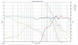
I get a deep null but there is phase overlap only on one side. Would that be a problem? Is there any way to fix this and make the phase responses match better? I've played around with the components, changing values, adding or removing parts, but nothing so far has fixed it. Am I overlooking something?
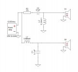
Speaker drivers that I'm using:
Dayton Audio AMT Mini-8
Dayton Audio DS135-8 5"
So I'm building some compact-ish bookshelf speakers and some input on my crossover design would be very much appreciated.
I get a deep null but there is phase overlap only on one side. Would that be a problem? Is there any way to fix this and make the phase responses match better? I've played around with the components, changing values, adding or removing parts, but nothing so far has fixed it. Am I overlooking something?
Speaker drivers that I'm using:
Dayton Audio AMT Mini-8
Dayton Audio DS135-8 5"
Attachments
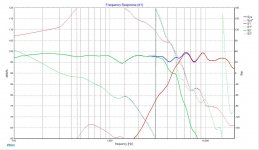
Firstly, I notice that by the time phase is 90 degrees apart near 2k3, the tweeter is down by almost 30dB. So it's not the end of the world.
I can see your slopes are a little different, you might consider working to a target slope.
Are your measurements clean?
I can see your slopes are a little different, you might consider working to a target slope.
Are your measurements clean?
I don't think that looks too bad.
When you get into something like this keep your expectations realistic. You can't achieve "textbook" results in the real world.
Dave.
When you get into something like this keep your expectations realistic. You can't achieve "textbook" results in the real world.
Dave.
Thanks for the reply.Firstly, I notice that by the time phase is 90 degrees apart near 2k3, the tweeter is down by almost 30dB. So it's not the end of the world.
I can see your slopes are a little different, you might consider working to a target slope.
Are your measurements clean?
A target slope means same slopes on both drivers?(dumb question, sorry)
I got my FRD and ZMA from the dayton audio website which probably isn't optimal.
Thanks for the reply, Dave.I don't think that looks too bad.
When you get into something like this keep your expectations realistic. You can't achieve "textbook" results in the real world.
Dave.
I agree whole heartedly but this is a learning experience for me so finding more about things that I might have missed or did wrong is extremely beneficial.
I had a quick look with the parts express FRD+ZMA files.
How is the DS135 getting you 95db? It should be more like 85db. Something's wrong.
How is the DS135 getting you 95db? It should be more like 85db. Something's wrong.
HiI had a quick look with the parts express FRD+ZMA files.
How is the DS135 getting you 95db? It should be more like 85db. Something's wrong.
In the images its powered by 20w. If I change the wattage of the amp to 1w it goes back to 85db.
You need to take into consideration the Y and Z axis offsets between tweeter and woofer. When plug in those numbers, the phase alignment at the crossover will be a lot more different than the idealized version where acoustic center of woofer and tweeter is at single physical point as in your current simulation.
That's right, and add to that the baffle step.
Xsim can make these for you as an *.frd file and you can use them as an overlay. If you have any difficulty just ask. It's not unusual to use 4th order targets (this doesn't mean 4th order filters)
Usually it does. Even where adjustments are to be made it can be better to start from this known position.A target slope means same slopes on both drivers?
Xsim can make these for you as an *.frd file and you can use them as an overlay. If you have any difficulty just ask. It's not unusual to use 4th order targets (this doesn't mean 4th order filters)
Hello.You need to take into consideration the Y and Z axis offsets between tweeter and woofer. When plug in those numbers, the phase alignment at the crossover will be a lot more different than the idealized version where acoustic center of woofer and tweeter is at single physical point as in your current simulation.
So what would be the best way to do that? I just measure the distance between woofer and tweeter centers and input that into mod delay of the tweeter for example or measure the distance divide into two and plug those numbers into both mod delays of the woofer and tweeter(as if the mic was between both, which seems logical)?
I will definitely fiddle around with it and see what happens.That's right, and add to that the baffle step.
Usually it does. Even where adjustments are to be made it can be better to start from this known position.
Xsim can make these for you as an *.frd file and you can use them as an overlay. If you have any difficulty just ask. It's not unusual to use 4th order targets (this doesn't mean 4th order filters)
Hello Kel159
Do you know of the oldest trick in the HiFi book ?
For two-way speakers we used to use 2nd order butterworth filters in the old days.
A 2nd order BW filter has the HP section "leading" 90° in phase an the LP section "lagging" 90° in phase, i.e. a combined 180° out-of-phase.
Then reverse the wires to ONE of the speakers.
Worth a try.
(of course, the front plate needs to be slanted or stepped in order to make the phase-planes of the two speakers somewhat coincident).
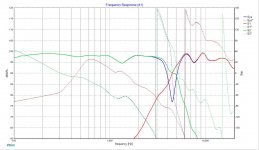
Ok yall so this is where I'm at currently.
As you can see the new FS is not as flat with 6db amplitude between highest and lowest point(used to be 4). The reverse null is not as deep as before. The phase plots look a lot better though.
So I guess my question is, is this set up generally better? Should I prioritize phase matching or reverse null depth/width etc. Also what is a good reverse null depth and is this enough?
Attachments

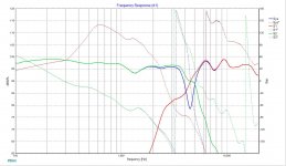
Firstly, you need to get rid of C4. It is a short circuit hazard for your amp at higher frequencies.
Secondly, the reverse null test is not necessary. This is something people use when they don't have phase information.
Secondly, the reverse null test is not necessary. This is something people use when they don't have phase information.
Soooo I don't have to look for a reverse null?Firstly, you need to get rid of C4. It is a short circuit hazard for your amp at higher frequencies.
Secondly, the reverse null test is not necessary. This is something people use when they don't have phase information.
No, but if it makes you feel better 😉 You see the information is in the phase plots. If the phase lines up where the responses cross then there would be a null, it's as simple as that. In fact some crossovers aren't even supposed to line up that way, there would be no null for them.
- Home
- Loudspeakers
- Multi-Way
- Help needed with 2-way crossover design (phase issue?)(first time build)