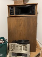
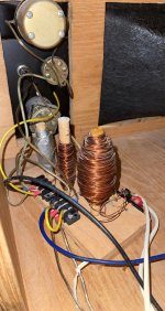
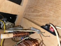
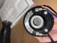
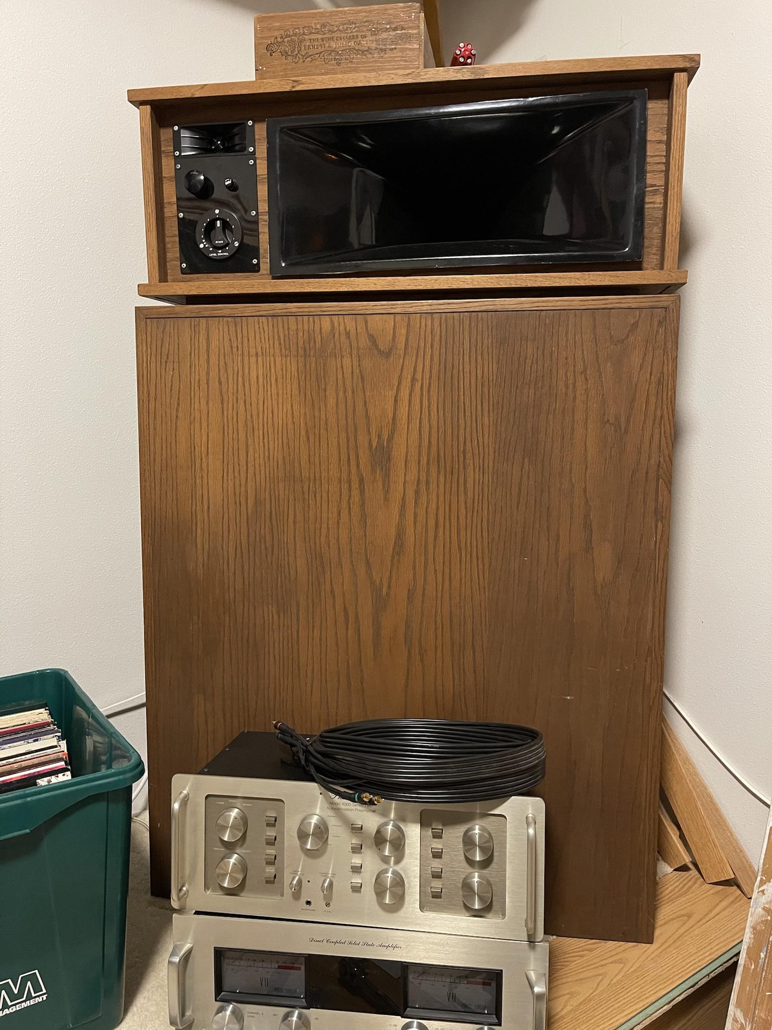
So it’s been an easy week in school so I decided to try my dad’s corner horns he built 50 years ago. After moving a couple wires around to what would make most sense, I managed to get them working. Only problem is, they sound bad! I’m just a high school kid but i'm guessing it’s from the old wiring and crossover components. Since you guys will know best, how should I approach the renewal of these beautiful speakers? Recommendations on new, quality parts?
Last edited:
I'll make a guess that you have a three way, with two piezo driven horns and a bifurcated bass horn. There are two level controls and a fuse. The crossover seems to have a few inductors.
Are all the drivers working and adjusted?
Are all the drivers working and adjusted?
They’re working fine except the woofer being staticky but that is from a poor wire connection I believe. What do you mean by adjusted?
The two volume control looking devices at the top left of the speaker should control the level of mid and tweeter. If these have been bumped, then you would turn them both to minimum and take it from there.
If your woofer is sounding scratchy, I'd question whether it is playing loud enough for things to sound right. Possibly a dirty connection, possibly voice coil damage. Check the connections first.
First thoughts are to snip and strip the tips of the speaker wire and clean all terminals.
Then, note the positions of all controls on the amps (take a good photo), move them and return them, then study their function.
Those small tweeters look like EV T35.
Look for hidden caps to go along with those home spun chokes.
Maybe turn the woofers 180 to help reverse possible sag. Coils may not be damaged just rubbing.
Look for hidden caps to go along with those home spun chokes.
Maybe turn the woofers 180 to help reverse possible sag. Coils may not be damaged just rubbing.
The two volume control looking devices at the top left of the speaker should control the level of mid and tweeter. If these have been bumped, then you would turn them both to minimum and take it from there.
If your woofer is sounding scratchy, I'd question whether it is playing loud enough for things to sound right. Possibly a dirty connection, possibly voice coil damage. Check the connections first.
First thoughts are to snip and strip the tips of the speaker wire and clean all terminals.
Then, note the positions of all controls on the amps (take a good photo), move them and return them, then study their function.
Alright I will try that. I’m planning on rewiring everything with new wire and solder in the coming days. I will remember to clean the terminals then.
Perhaps you have 2nd order HP on both horns and 1st on the woofer. Caps might need updating. Can you draw a schematic?
I’m not exactly sure what you mean by the first sentence. And are you asking for a wiring diagram?
You need some test equipment. Here's what I'd do.
1. Go find a nice, long Pink noise .mp3 recording and put it on an SD card.
2. Many small amplifiers on ebay read SD cards and have the full audio spectrum power out. Get one. Get a battery pack setup for it; some even use 5V!
3. You phone's mic is good enough to tell if the three drivers in these cabs are working and if they're balanced. You'll need an audio spectrum analyzer program for your phone. Both free and paid version will work.
4. Put the SD card in the amplifier, connect it to one of the speakers and power it up. It should start playing the .mp3 file on the card. It will sound like a waterfall...
5. Bring up your phone app, select the best microphone on the phone (if the app doesn't do that for you) and have it display a spectrum, 20 - 20kHz.
6. When you set the app to do octave measurements, it should produce a somewhat "flat" frequency response - see attached. You can increase the resolution by choosing the octave fraction (1/6); it should still display a fairly flat curve on the phone screen.
If there's blocks missing, that would indicate a driver not working. A block might be all indication above 10kHz for example. Or everything below 1kHz. Or the frequency levels that are in-between.
If they're all there, but each section looks like it's on it's own shelf in level, that indicates the level controls need to be adjusted. Adjust until all three blocks align as close to a single straight line as you can get it.
Using your phone and a cheap amplifier off ebay, you can diagnose these speakers and perhaps set them up for how your dad intended them to run. If not, then you can fix it by perhaps replacing some of the electrical work he did, obviously building components by hand. Even if you replace the crossovers he made with something entirely different, you can still use your phone / amp combo to measure the results. And make the adjustments, to get it right.
Attachments
Last edited:
The woofer inductor looks like paralleled thin zip cord (?) Klipsch used 2.5mH "1st order" with 4 ohm rated woofers.
IF just a cap feeds the T-35 rectangular horn tweeter, then that probably should not be more than 2.5-3uF value. (I've popped T35 diaphragms...)
If you can open the woofer chamber, try testing the woofer disconnected from the crossover by itself with a flashlight battery, then music, listening for static or voice coil rubbing. Take a picture of the woofer.
Also, upload a picture of the midhorn's driver. There should be a capacitor associated with it - perhaps in the 12 to 30uF range.
The piezos are like a capacitor so don't require a crossover for protection.
Look at this Speakerlab K crossover schematic. Save it.
https://community.klipsch.com/uploads/monthly_10_2013/post-22684-13819359467024.jpg
That is a great looking horn build.
You can salvage the L-pads and it would not be terribly expensive to build new crossovers like say a Klipsch "A" network. Parts Express has steel laminate chokes with reasonably low resistance "cheap" under their Dayton name. They look quite good.
Klipsch used an autoformer to attenuate midhorns in the Heritage series. Your pads will do fine for that duty.
btw - The basshorn probably could be run without any crossover. Bass may be tighter that way as there may be a fair amount of resistance in the crossover's woofer inductor.
Here's a 2.5 milluHenry inductor with only 1/3 ohm resistance for $5.39. That would be like Speakerlab used in their 8 ohm
woofer crossover in the schematic linked above
Dayton Audio 2.5mH 18 AWG I Core Inductor Crossover Coil
Last edited:
And be3 careful with that EV tweeter because it is next to impossible to find spares nowadays.
Regards
Charles
P.S: It is a very nice looking horn build.
Regards
Charles
P.S: It is a very nice looking horn build.
I’m not exactly sure what you mean by the first sentence. And are you asking for a wiring diagram?
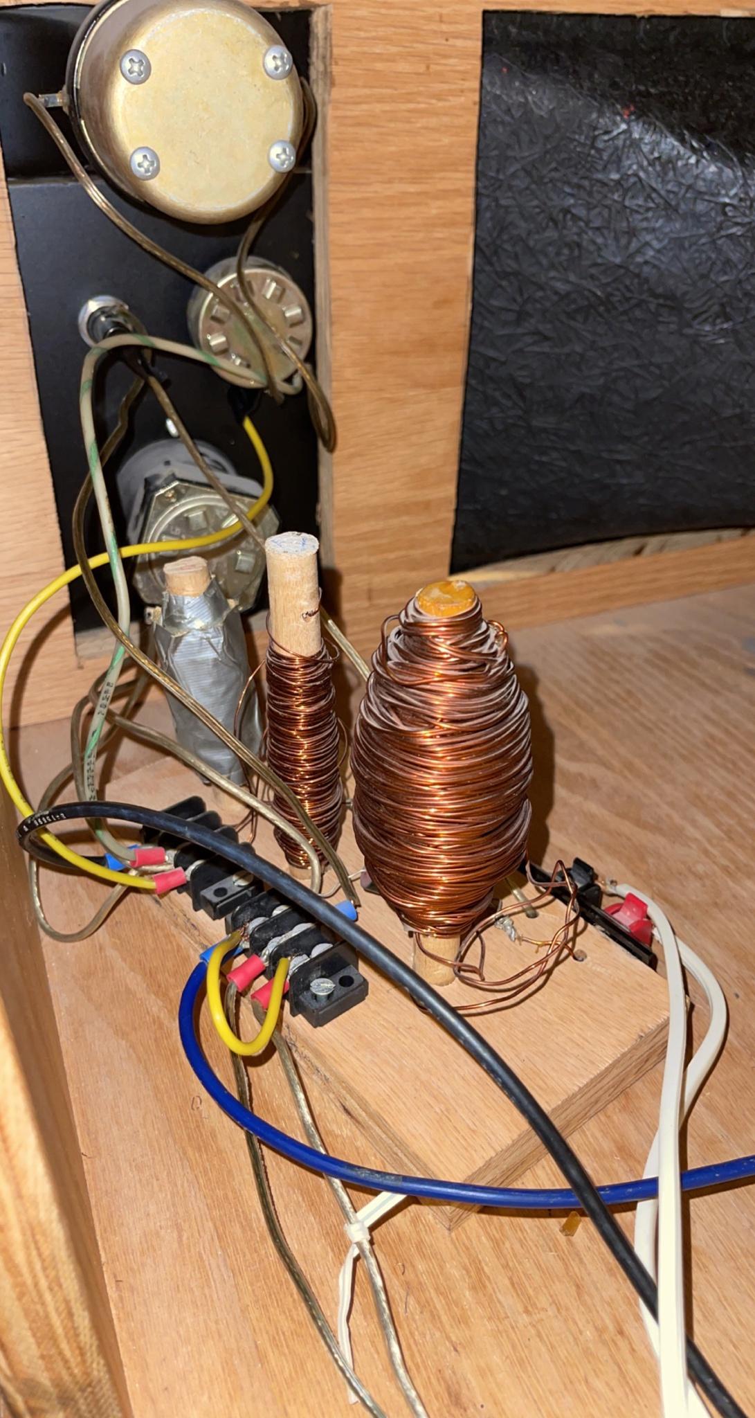
It is likely you have a 2nd order filter on the small tweeter. That is a cap in series and one of the chokes in parallel with the driver. That is a High Pass filter.
It is likely you have either the same configuration on the midrange horn allowing it to run unfiltered on the top end or both a cap and coil in series, cutting off the top and bottom but only as a 1st order filter.
The woofer likely has just a choke in series making it also a 1st order filter.
You need to trace out a wiring diagram, complete with the capacitor values so we can suggest what's best. You should also open the boxes up and give us names and or numbers on the individual drivers. We're pretty sure the small tweeters are the EV T35's but the other two are important.
Is the thing wrapped in duct tape a choke coil as well?
I suspect there are no piezo units there.
Last edited by a moderator:
It is likely you have a 2nd order filter on the small tweeter. That is a cap in series and one of the chokes in parallel with the driver. That is a High Pass filter.
It is likely you have either the same configuration on the midrange horn allowing it to run unfiltered on the top end or both a cap and coil in series, cutting off the top and bottom but only as a 1st order filter.
The woofer likely has just a choke in series making it also a 1st order filter.
You need to trace out a wiring diagram, complete with the capacitor values so we can suggest what's best. You should also open the boxes up and give us names and or numbers on the individual drivers. We're pretty sure the small tweeters are the EV T35's but the other two are important.
Is the thing wrapped in duct tape a choke coil as well?
I suspect there are no piezo units there.
I have no idea what the capacitor values are but here are pictures.
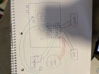
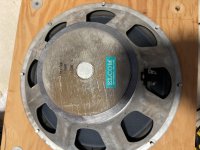

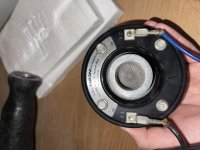
(keep in mind I am no professional)
And yes, the thing wrapped in duct tape is a choke coil.
The black capacitor has numbers on it. What are they?
The silver capacitor is electrolytic bipolar, because it has indents on both ends. The numbers might be on the bottom. Your looking for a xx mf yy volts.
That EV horn tweeter is priceless, I'd put a 8 ohm 10 w resistor series to keep pops of bad connections from blowing it. It is likely much more efficient than the woofer.
Before buying new inductors, I'd buy a $35 inductor meter from parts-express to measure what the old ones are. May be exactly what you need.
Then do the measurements. I'm happy for you that you bought a smart phone. I didn't. Details matter on making a speaker sound good. You can try woofer separately on alligator clip leads to amp to see if it scratches that way. If so, in the trash can.
In USA this mono amp for $40 is about the best bargain I know of. $35 shipping to my location. Peavey MMA 8150T - 8 channel Modular Mixer/Amplifier | eBay
MMA-8150t. 150 clean amps, if it works. Mine did.
If it does work, it will last a lot longer than some piece of import trash. If doesn't work, after repaired same thing. Designed for 24/7 use in warehouses, but <.2% hd.
Last edited:
You can try woofer separately on alligator clip leads to amp to see if it scratches that way. If so, in the trash can.
All good advice except this. As mentioned it might be cone sag. Turn it 180º, leave it in a warm room for one or two days then try it.
The roll surround looks to have some aging/damage.
Right. Try not to disturb them except to disconnect them before measuring their value.Before buying new inductors, I'd buy a $35 inductor meter from parts-express to measure what the old ones are. May be exactly what you need.
FWIW, other than. nostalgia, I'd consider a modern pc board with standard disconnects and enough area to mount new components, a $6 Dayton laminated steel core ("I" bar) woofer inductor.
If there is no damage to the woofer's voice coil, then you could re-do the foam surrounds. Perhaps there's a cloth surround which would work and last longer. You would need double thick cardboard gaskets, or make a spacer to ensure the cone cannot slam into the motorboard.
25uF cap
Dayton Audio DMPC-25 25uF 250V Polypropylene Capacitor
Crossover board
Crossover PC Board 3-Way 12 dB Large 5" x 9"
Here's the Klipsch Type A network - the 3dB attenuation of its mid-horn using an autoformer reflects twice
The driver’s impedance so a cap half of normal value is used. (12uF vs 24uF in this case). Later when high power amplifiers such as Carver's Phase Linear came onto the scene, the tweeter network was changed to 3rd order with Zener diode clamping protection.
https://community.klipsch.com/uploa...atic.jpg.65604c277fbeffeb4b9f2a14c19f995a.jpg
Here's a simplified drawing of EV's Sentry IV network with EV 1823M mid-horn driver
https://i.imgur.com/TI1FV68.jpg
I wonder if your Dad's mid-horn is a Community product - ? - its much nicer looking imo than EV's SM120 used in Sentry IV.
I've seen 15 inch NOS Eminence woofers suitable for K-horn at Ebay sometimes as low as $45 new - perhaps those days are gone.
Klipsch typically used a 2 inch diameter voice coil, fs 30-40Hz, qts is around 0.4 on my K33E.
Last edited:
- Home
- Loudspeakers
- Multi-Way
- Help Needed for Old Horns
