Hai, I am building this EL84 SE amp.Now I am trying to design the power supply stage for the amp.
Specs: it must use a 6CA4/EZ81 tube
output power after filter must be around 275V ~300V
what do you guys think 😀
Help apreciated 😉
Specs: it must use a 6CA4/EZ81 tube
output power after filter must be around 275V ~300V
what do you guys think 😀
Help apreciated 😉
Do you have a schematic?.....
Not sure what you are asking......do you need help selecting a power transformer and perhaps a choke?
Are you familiar with PSUDII?
Not sure what you are asking......do you need help selecting a power transformer and perhaps a choke?
Are you familiar with PSUDII?
It is possible
Below is a link to the datasheet.
http://tdsl.duncanamps.com/pdf/ez81.pdf
The one thing to keep in mind is that these tubes require anode limiting resistors to maintain tube life. The more resistance you have in the power supply, the more sag / less regulation you will get.
A transformer with a 250-0-250 AC tap will give you around 300 volts DC with a CRC filter.
A transformer with a 350-0-350 AC tap will give you around 300 volts DC with a critical choke input filter. Choke 4 henries or above right off the rectifier with a CRC following. This will improve regulation.
Nope no schematic
Yes i do have the softwar but i dont really understand how it work
Care to help?
I need help on selecting the transformer.I dont want to use choke input filter only resistor and cap input stage
Yes i do have the softwar but i dont really understand how it work
Care to help?
I need help on selecting the transformer.I dont want to use choke input filter only resistor and cap input stage
How do i calculate the anode resistor? 😀
Below is a link to the datasheet.
http://tdsl.duncanamps.com/pdf/ez81.pdf
The one thing to keep in mind is that these tubes require anode limiting resistors to maintain tube life. The more resistance you have in the power supply, the more sag / less regulation you will get.
A transformer with a 250-0-250 AC tap will give you around 300 volts DC with a CRC filter.
A transformer with a 350-0-350 AC tap will give you around 300 volts DC with a critical choke input filter. Choke 4 henries or above right off the rectifier with a CRC following. This will improve regulation.
Any tube rectifire is welcomeWhy must it use 6CA4/EZ81? 6BW4 are cheaper.
maybe evan SS rectifire?
Software simulations have their place, but measurements, at the bench, rule.
I have no idea what is available in S.E. Asia. However some off the shelf parts seem to be suitable.
A Hammond 369HX power transformer and Triad C-14X filter choke look about right. Use a CLC filter. Start with a small cap., say 2.2 μF. in the 1st position and measure the rail voltage, with the supply loaded down. Increase the amount of capacitance in the 1st position, until the loaded down supply provides what's needed. Use a 100 μF. part in the 2nd (reservoir) position.
Using the smallest amount of capacitance in the 1st position, consistent with getting the job done, places minimal stress on both the power trafo and vacuum rectifier. The choke shields the tube and trafo from the large reservoir capacitor.
BTW, the 5 VAC winding of the 369HX can be voltage multiplied and regulated for use in energizing the small signal tube heater(s) with DC.
How do i calculate the anode resistor? 😀
Attachments

Parts in malaysia is quite hard to get.Software simulations have their place, but measurements, at the bench, rule.
I have no idea what is available in S.E. Asia. However some off the shelf parts seem to be suitable.
A Hammond 369HX power transformer and Triad C-14X filter choke look about right. Use a CLC filter. Start with a small cap., say 2.2 μF. in the 1st position and measure the rail voltage, with the supply loaded down. Increase the amount of capacitance in the 1st position, until the loaded down supply provides what's needed. Use a 100 μF. part in the 2nd (reservoir) position.
Using the smallest amount of capacitance in the 1st position, consistent with getting the job done, places minimal stress on both the power trafo and vacuum rectifier. The choke shields the tube and trafo from the large reservoir capacitor.
BTW, the 5 VAC winding of the 369HX can be voltage multiplied and regulated for use in energizing the small signal tube heater(s) with DC.
If i can't get the parts i need than most likely i will go SS rectification
PS.dont talk about Ebay
If you can source a Triad N-68X isolation trafo, which has dual primaries, a high performance B+ PSU that's inexpensive can be built. You use the "full wave" doubler topology shown in the attached "El Cheapo" schematic.
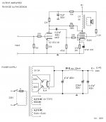
The signal topology shown in the attached RH84 schematic can be a good point of departure for a SE EL84 amp build. An obvious improvement is to regulate EL84 screen grid B+. A nice way to regulate g2 B+ is using stacked 0A2 and 0B2 glow tubes.
The signal topology shown in the attached RH84 schematic can be a good point of departure for a SE EL84 amp build. An obvious improvement is to regulate EL84 screen grid B+. A nice way to regulate g2 B+ is using stacked 0A2 and 0B2 glow tubes.
Attachments

Thanks for the schematic,I am now on a quest to finding the output transformer and power transformer 😀If you can source a Triad N-68X isolation trafo, which has dual primaries, a high performance B+ PSU that's inexpensive can be built. You use the "full wave" doubler topology shown in the attached "El Cheapo" schematic.
The signal topology shown in the attached RH84 schematic can be a good point of departure for a SE EL84 amp build. An obvious improvement is to regulate EL84 screen grid B+. A nice way to regulate g2 B+ is using stacked 0A2 and 0B2 glow tubes.
Last edited:
Thanks for the schematic,I am now on a quest to finding the output transformer and power transformer 😀
Try this , Tube Depot.
I am from Penang, now in NYC.New york 🙂
- Status
- Not open for further replies.
- Home
- Amplifiers
- Tubes / Valves
- HELP NEEDED for a 6CA4/EZ81 power supply