I picked up this tube amplifier from eBay recently, and I've been puttering about with it, trying to get it working properly.
 GE RP-1170A Tube Amplifier by Wigwam Jones, on Flickr
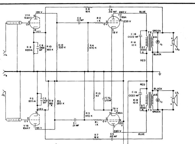
This is a General Electric RP-1170A, which consists of a 12AX7, two 7198A output tubes, and a 5Y3 rectifier. All tubes appear original GE, and appear to be working (I do not have a tube tester yet).
I found a dead output transformer on one channel, so I drilled out the rivets and replaced both output transformers with the cheap 5K to 8 Ohm SE output transformers they sell on Antique Electronic Supply. Based on tube data sheets I found for the similar 6BQ5 tubes, I thought 5K would be OK.
So here is the first mystery. I found a copy of the schematic online, and if this is not a misprint, it seems to be showing that the primary side of the output transformers are 500 Ohm! How can this be possible with these tubes?
 62_General Electric_RP1170_schematic by Wigwam Jones, on Flickr
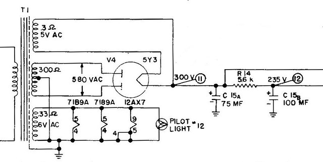
And here is the second mystery. The amp came with the typical cardboard tube multi-capacitor for the power supply. 75uf @450V, 100uf @450V, and 100uf @25V. Doesn't 75uf seem a bit high for the first capacitor in a CRC power supply after the 5Y3 tube? I guess it must be correct, since a) it still works (although of course I am replacing it) and b) GE designed it this way, and apparently they knew what they were doing.
 62_General Electric_RP1170_power_supply by Wigwam Jones, on Flickr
So my questions are:
1) Is the output transformer supposed to have a 500 Ohm primary, or is this a misprint and it should be 5K?
2) Is it really OK to use a 75uf electrolytic capacitor as the first cap in a CRC power supply after a 5Y3 rectifier tube?
Thanks for any assistance you can give me!
GE RP-1170A Tube Amplifier by Wigwam Jones, on FlickrThis is a General Electric RP-1170A, which consists of a 12AX7, two 7198A output tubes, and a 5Y3 rectifier. All tubes appear original GE, and appear to be working (I do not have a tube tester yet).
I found a dead output transformer on one channel, so I drilled out the rivets and replaced both output transformers with the cheap 5K to 8 Ohm SE output transformers they sell on Antique Electronic Supply. Based on tube data sheets I found for the similar 6BQ5 tubes, I thought 5K would be OK.
So here is the first mystery. I found a copy of the schematic online, and if this is not a misprint, it seems to be showing that the primary side of the output transformers are 500 Ohm! How can this be possible with these tubes?
62_General Electric_RP1170_schematic by Wigwam Jones, on FlickrAnd here is the second mystery. The amp came with the typical cardboard tube multi-capacitor for the power supply. 75uf @450V, 100uf @450V, and 100uf @25V. Doesn't 75uf seem a bit high for the first capacitor in a CRC power supply after the 5Y3 tube? I guess it must be correct, since a) it still works (although of course I am replacing it) and b) GE designed it this way, and apparently they knew what they were doing.
62_General Electric_RP1170_power_supply by Wigwam Jones, on FlickrSo my questions are:
1) Is the output transformer supposed to have a 500 Ohm primary, or is this a misprint and it should be 5K?
2) Is it really OK to use a 75uf electrolytic capacitor as the first cap in a CRC power supply after a 5Y3 rectifier tube?
Thanks for any assistance you can give me!
Back in the day tubes were cheap and easy to replace, but yes the 75uF is way to large. Try a 22uF. Or put some UF4007 in series with the plates of the 5Y3.
The 500R primary is most likely the DC resistance.
The 500R primary is most likely the DC resistance.
1. These OT are not very good, they have small iron /it's very easy to saturate it in SE/ and too many wires for big L, and primary R 500ohm is very big. I prefer for Poutput 3-5-W big iron /OT about 20-30 W/ with less coils and primary R about 100 ohm. More iron will give You big sound.
2. First el. cap must be no more 47 uF. Big cap will short rect. tube in first moment to charging. Better use 75 uF parallel to second cap 100uF for better filtering.
There is depend between Ra 12AH7 that is 220 kohm, and cathode cap, that must be about 100 uF and interstage cap, that must be 0.033 uF for better dynamic mode.
Last edited:
Back in the day tubes were cheap and easy to replace, but yes the 75uF is way to large. Try a 22uF. Or put some UF4007 in series with the plates of the 5Y3.
Thank you! I was considering using some diodes in series with the plates for the reason that this will be (if it sounds half-way decent when done) a gift for a friend, and I don't want to have it let the magic smoke out down the road. I had read this is an old trick for guitar amps to keep them running in case they blow up a rectifier tube while playing on stage.
So if I do that, then will I also be seeing a voltage change in the output? Any other issues to consider, or just solder them in and call it good?
The 500R primary is most likely the DC resistance.
OK, I can buy that. Struck me as strange. Thanks!
1. These OT are not very good, they have small iron /it's very easy to saturate it in SE/ and too many wires for big L, and primary R 500ohm is very big. I prefer for Poutput 3-5-W big iron /OT about 20-30 W/ with less coils and primary R about 100 ohm. More iron will give You big sound.
Thanks, I think I am following what you are saying.
I agree that these are not high-quality output transformers, but they are about the same size/weight as the originals, perhaps a bit larger, and they are inexpensive.
https://www.tubesandmore.com/products/P-T31
If I happen to come across some better output transformers for cheap, I would certainly consider them. But this amp came out of a 1961 General Electric phonograph player. It was never designed for Hi-Fi to begin with. It's 'medium fidelity' at best. No point trying to make a silk purse out of a sow's ear, right?
2. First el. cap must be no more 47 uF. Big cap will short rect. tube in first moment to charging. Better use 75 uF parallel to second cap 100uF for better filtering.
Well, I do agree that 75uF is bad, but bear in mind that it will NOT bow up in the first second, because it has been running in this circuit since 1961 and apparently it didn't blow up so far...
I am definitely thinking of replacing it with a smaller cap however. Thank you!
12AX7 is not very good tube for pre amp. Better use 12AT7 with Ra about 30-40 kohm and cathode cap about 330 uF and interstage cap about 0.047 uF. Legs of both tubes are the sames. /First cap with big uF is dangerous for rect. tube./
20 W OT EDCOR costs about 40 $.
20 W OT EDCOR costs about 40 $.
Last edited:
So if I do that, then will I also be seeing a voltage change in the output? Any other issues to consider, or just solder them in and call it good?!
You will still have the same stock voltage because the plate resistance of the rectifier tube is unchanged and in series with the diodes, think of the rectifier tube now as some fancy resistors after the diodes. Just solder em in and you should be good to go.
12AX7 is not very good tube for pre amp. Better use 12AT7 with Ra about 30-40 kohm and cathode cap about 330 uF and interstage cap about 0.047 uF. Legs of both tubes are the sames. /First cap with big uF is dangerous for rect. tube./
I have thought about that as well. I notice that I really need to attenuate my input, it seems I am overloading the amp with a modern pre-amplifier.
If I change the 12AX7 to a 12AT7, then you are talking about changing R5 & R8 on my schematic as well as C5 & C6? I am sorry, I do not know what 'interstage' cap means.
20 W OT EDCOR costs about 40 $.
Yes, I have looked. In my case, time is a factor and I have been told that 6 weeks is not unusual for delivery. I unfortunately do not have that long. I agree that this would be a nice substitution.
You will still have the same stock voltage because the plate resistance of the rectifier tube is unchanged and in series with the diodes, think of the rectifier tube now as some fancy resistors after the diodes. Just solder em in and you should be good to go.
Excellent, thank you. I will do that.
Perhaps the rectifier survives the big input cap when the PT has a high impedance HT winding? This reduces the charging current.
I have seen datasheets listing different max cap size depending on transformer resistance.
Don't know if that is the case here though as 75u is very large.
I have seen datasheets listing different max cap size depending on transformer resistance.
Don't know if that is the case here though as 75u is very large.
Perhaps the rectifier survives the big input cap when the PT has a high impedance HT winding? This reduces the charging current.
I have seen datasheets listing different max cap size depending on transformer resistance.
Don't know if that is the case here though as 75u is very large.
Interesting question. I'm afraid this is way out of my experience. I notice the schematic lists the PT HT winding as 300 Ohm. I don't know if that is a high impedance for this sort of PT or not, though.
The whole thing just strikes as odd, considering that GE apparently designed it this way. I get what famousmockingbird means about the fact that tubes were cheaper and easy to replace back in the day, but I still don't think that GE would intentionally use bad design. There must have been some reason that they broke this 'rule' about the first cap in a CRC filter, but I just don't know what it is.
R5 and R8 about 400 ohm. Interstage caps are C1 and C2 between pre amp and 6BQ5.
Got it, thanks. I thought C1 and C2 were known as 'coupling caps'. I am learning bit by bit! 😀
Your new preamp maybe will look.....12AT7. Rcathode 390 ohm, Ccathode 330 uF, Ra about 40 kohm /with tube current about 5-8 ma/, interstage cap 0.047 uF....if You decide to change pre tube....
For better filtering and to decrease humm /in Your place, if I'm/ I will change the schem. of PS.
1. First cap - 47 uF. /You don't need diodes and resistors/. On 47 uF ripples are about 5 V, that is very bad, if OT is connected to first cap.
2. After it resistor 50 ohm/10 W.
3. Second cap /100 + 75 uF/ or new cap 470 uF/400 V and go to primary of OT.
4. After them 5.6 kohm.
5. Third cap 100 uF and to preamp and second grid of 6BQ5.
Last edited:
Series SS diodes provide additional PIV headroom. The need to heed the capacitance limit stated on the data sheet remains in force. The remark about tubes being cheap, back in the day, sums things up pretty well. FWIW, I say put a proper CLC filter in there and have the rectifier last a long time. A 22 muF. part in the 1st position rates to be safe. A 3.5 H./150 mA. Hammond 157Q provides ripple rejection and isolation from the remainder of the PSU filter.
The 12AX7 is adequate for driving the full pentode mode "finals".
A look at the size of the voltage amp cathode resistor bypass caps. tells you bass extension is very poor. That's consistent with puny O/P trafos.
Good luck in sourcing replacement 7189As. The replacement O/P tube to use is the Russian 6p14p-ev, AKA EL84M. The Russian tube is a TOUGH, good sounding, 7189 equivalent. Pay attention to the pin out differences between the 7189 and the 7189A.
BTW, I don't see grid to ground resistors in the 'X7 circuitry. 100 KOhms is about right.
Yes the diodes just help with the flash over, but with the 300 ohm secondary resistance and the fact that it is class A I don't see this rectifier being abused too much. The high capacitance is necessary to get ripple down. You can try a lower cap value and live with some hum or do as Eli suggests and add a choke after a 22uF C input filter.
Never assume that GE knew what they were doing with this circuit...
Many times interns were given these simple task of slapping circuits together and doing quick calculations on the back of an envelope...
The perception of a room full of seasoned senior design engineers working out all the numbers for such a simple design is ridiculous and major loss of money...
They saved the muscle designers for 3 phase motors and motor controls as well as vacuum tube R&D ...
Thanks, guys, I really appreciate all the insight and wisdom you're giving me. I believe I understand what I'm being told, and I'm doing my best to digest it all.
- Status
- Not open for further replies.
- Home
- Amplifiers
- Tubes / Valves
- Help me understand this 7189A SE tube amp?