I've done lots of single ended projects and understand fully differential circuits, but I haven't paid to much attention to balanced input and (line level) output stages.
Does anybody mind help explaining the differences, including schematics? In an power amplifier, by the the time the balanced input hits the positive input to the first diff pair of the amp is it effectively converted to single ended? Or is the ground always isolated? As in, the cold is used for the audio ground?
In a preamp, does the balanced input effectively travel "fully differential"? If you're doing some kind of filtering such as an active XO, does both the hot and the cold need to have the exact same passive elements for filtering?
Balanced signals are usually used just to drive cables and are converted to single ended as soon as they enter the equipment
Last edited:
Balanced signals are usually used just to drive cables and are converted to single ended as soon as they enter the equipment
So as I stated in the OP, the hot and cold are converted into single ended as soon as it touches the positive input of the amplifier diff pair? If so, my follow up is if the "COLD" signal is used as the audio ground or is the "GROUND" signal of the balanced input now used as the actual ground. Schematic example?
Do you mean the power amp? The simplest, most common conversion is to use the differential inputs of an opamp.So as I stated in the OP, the hot and cold are converted into single ended as soon as it touches the positive input of the amplifier diff pair?
If so, my follow up is if the "COLD" signal is used as the audio ground or is the "GROUND" signal of the balanced input now used as the actual ground. Schematic example?
Balanced ground is used as signal ground Balanced Line Driver & Receiver
On Hypex support site in white paper area suggest download and read the one named "The G Word, or How to Get Your Audio off the Ground" (link https://www.diyclassd.com/p/application-notes-white-papers/) and if remember right at Rane and Jensen Trasformer web sites there is also some nice papers.
Does anybody mind help explaining the differences, including schematics?
This is a large subject area with many variations. Here's a worthwhile general article.
The Fully Balanced Power Amplifier - Advantages and Design Challenges - HomeTheaterHifi.com
Balanced really means:
Balanced Impedance and that really applies to the connection arrangement
It's the impedance of the connection that is balanced.
That requires the connection cable to be balanced impedance type, the transmit end needs to be balanced impedance type and the receive end needs to be balanced impedance type.
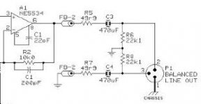
Have a look at a balanced output stage. The two signal lines have the same resistances (R5=R7 & R6=R8) and the same capacitances (C3=C4). If it's made symetrically then the inductances will also be very similar.
The balanced input stage has the same features: the input resistances (R3=R7, R1=R8, R2=R9, R4=R6), capacitances (C1=C5, C3=C4) and by symmetry the inductances are all equal.
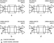
Note, that there is no ground connection in the signalling.
The two enclosures are connected via Pin1 at both ends. But ONLY the enclosure is connected to Pin1.
Note also, that even in the three unbalanced cable arrangements that the Pin1 are ALL connected to the enclosures at BOTH ends.
The signal cable gets connected to audio ground at one, or both ends, that makes the connection unbalanced.
Where the signals are NOT connected to the audio ground (option a) then the connection remains balanced IF the IMPEDANCES are balanced.
If RF attenuation is added, then the capacitors are taken to the enclosure at the input socket.
Balanced Impedance and that really applies to the connection arrangement
It's the impedance of the connection that is balanced.
That requires the connection cable to be balanced impedance type, the transmit end needs to be balanced impedance type and the receive end needs to be balanced impedance type.
Have a look at a balanced output stage. The two signal lines have the same resistances (R5=R7 & R6=R8) and the same capacitances (C3=C4). If it's made symetrically then the inductances will also be very similar.
The balanced input stage has the same features: the input resistances (R3=R7, R1=R8, R2=R9, R4=R6), capacitances (C1=C5, C3=C4) and by symmetry the inductances are all equal.
Note, that there is no ground connection in the signalling.
The two enclosures are connected via Pin1 at both ends. But ONLY the enclosure is connected to Pin1.
Note also, that even in the three unbalanced cable arrangements that the Pin1 are ALL connected to the enclosures at BOTH ends.
The signal cable gets connected to audio ground at one, or both ends, that makes the connection unbalanced.
Where the signals are NOT connected to the audio ground (option a) then the connection remains balanced IF the IMPEDANCES are balanced.
If RF attenuation is added, then the capacitors are taken to the enclosure at the input socket.
Attachments
Last edited:
- Status
- Not open for further replies.
- Home
- Amplifiers
- Solid State
- Help me understand the balanced input and output stage (with schematics)