Hello, this is quite complicated to model, because of the common closed box. One driver would damp the resonance of the other due to the parallel cap.
Could you please help me to study and model this behavior?
Probably it has been used in the past or by you, thus any bibliography is appreciated.
Need to understand PRO&CONS. Thanks

Could you please help me to study and model this behavior?
Probably it has been used in the past or by you, thus any bibliography is appreciated.
Need to understand PRO&CONS. Thanks
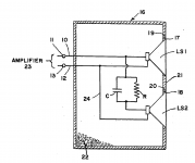
at 500Hz that cap has a reactance of 3.2 ohms - at 70Hz, 22.7 ohms. As frequency is lowered, more power is allowed to the bottom driver. at frequencies higher than 500, that cap is looking close to shorting the bottom driver so more current can flow through the top driver.
Look at Nestorovic's patent for similar - perhaps better (?) scheme
where the bottom driver can act as a passive radiator
https://www.diyaudio.com/community/threads/nestorovic-woofer-system.190529/
Look at Nestorovic's patent for similar - perhaps better (?) scheme
where the bottom driver can act as a passive radiator
https://www.diyaudio.com/community/threads/nestorovic-woofer-system.190529/
Attachments
A weird and wonderful idea! It's got me scratching my head after a bit of simulation. 😕
It is half a leg of the familiar series LC crossover often used in FAST designs where the bass is at right angles to the front-firing fullranger. It might work after a fashion, but I am not sure why you would do it.
I'd put the bass interaction on the back-burner for now, in favour of the electrical response.
What is the context of this design? Where did you find it?
Short version is that it's just the low-pass leg of a series crossover, & is usually employed to roll off the second driver above the baffle step frequency (or whatever the desired corner may be). It's not an exact equivalent to a parallel, but the analogy serves as an approximate. That's basically all there is to it on a conceptual level. You'd use it if your intended drivers would result in an excessively low system impedance when wired in parallel.
Last edited:
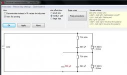
As Allen notes, it's not a pure low pass as the drivers are series wired, but it has that effect (it also has the effect of partly high-passing / HP shelving the other unit). For interest, the attached shows a nominal 8ohm resistive load, flat FR, impedance, coincident acoustic centres. Lower 'driver' shunted with a 160uF cap. No reason for that particular value BTW -'just because'.
Attachments
There shouldn't be baffle compensation. The combined response remains (eg flat) while the individual responses are redistributed. (There appears to be something wrong with the simulation.)
Nothing wrong with PCD7 last I checked, & the data / data entry is fine (as noted, it's just a flat amplitude & a fixed 8ohm load). Baffle step frequency (as in frequency) was intended simply as an example -I did say 'or whatever the desired corner [frequency] may be'. Apologies for the lack of clarity, it was poor phrasing. On the handful of occasions it's used with identical units, its main use that I know of is to reduce phase related destructive interference in the midband / HF.
I've used that concept on quite a few speakers, but with a much smaller value capacitor ( about 1 Uf - often a motor run polypropylene ) - this robs " Peter to pay Paul " - taking some of the treble of the lower driver and adding it to the top, reducing the " beaming " effect. It also means that both drivers are used for bass, making the most of box volume.

Well, mine isn't, both legs are default 8ohm resistive loads, but perhaps somebody else's is? Be that as it may, it does raise the interesting field of using dissimilar units, either as a compound (as Thorsten suggested years ago, providing you don't go too far apart in driver characteristics) or with them in independent chambers. No reason why that couldn't also be done with a parallel of course, but it's viable, in a broad sense.The sim is using mixed impedance drivers.
Hi, long story.
Don't ask me how I got to this absurd situation, but in short, this loudspeaker is a continuous adaptation of a speaker that I was wrong to design (two FR reflex in parallel!). The basic idea was to reinforce the bass of a full range in reflex box with a second paralleled FR reflex box. The result was a very fatiguing booming in the 65-80Hz range. But I don't want to talk about this. I'm publishing it just because you asked me. Difficult to admit, but it was a wrong borning design and I have now to adapt these cabinets. Thus, I gave up to one on the two parallel bass reflex bow, adding a third driver (to close one reflex tube hole) changing the upper case to a closed box with two series drivers inside. Crazy.
So...
It now sounds decently after hundreds of setup changes, it has an excellent load impedance, good directivity and no-more booming at 65-80Hz, but I can't simulate correctly the closed mid-bass behavior. Yesterday I tried with a frequency of 35 Hz and the excursions of both FRs in the closed case is the same, as if the first FR was not filtered by the capacitor at all, as if it were resonating with the second FR. In short, the closed box model seems to me to be much more similar to a damped passive speaker.
I can't stand trial and error without a minimum of modeling and explanation: this setup works well, but the Mid-bass theory is lacking. At the ears I would like to have more drum bass in the 100-300 Hz region, but this appers to me to be a limit of the Pluvia: any change I do in this direction I mess up all the rest. Thanks
Attachments
![20211117_131901[1].jpg](/community/data/attachments/942/942985-366b149a2de12acd29c639b62bc9a162.jpg?hash=NmsUmi3hKs)
Last edited:

I've often fancied giving this a try especially with Mark Audio drivers as they have BSC built in and therefore going to a 1.5 way configuration (parallel drivers with an inductor is series with one) might be a bit bass heavy. Using a cap in a series arrangement (as per the first post) reduces the displacement (for bass) for a given sound pressure level of the 'main' driver while maintaining a full range output. Advantage being increased power handling in the bass (doubling surface area) but maintaining point source in the higher frequencies. I have a spare Pluvia 7 and a 7MS, not identical but close enough, to give this a try. Like everything it takes a bit of effort to actually do it.
Last edited:
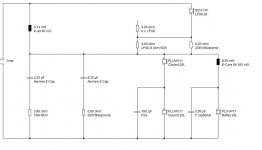
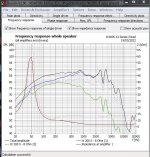
Here is an example of how you can make series drivers behave like one is not filtered and the other is being rolled off..

I am repeating what others have said to some extent. But ran a sim.
I impedance corrected a couple of basses to make things simple, and always a good idea with series filters anyway.
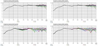
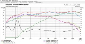
As noted, this capacitor circuit is NOT bafflestep. It transitions twin fullrangers to a single fullranger at mid frequencies with some changes to power response and phase, which ends up around 90 degrees between the two units.
Frequency response on axis is unchanged from a single driver. The top dotted line is the overlapped responses of the individual drivers without the capacitor. The bottom dotted line is the impedance without the capacitor.
Personally, I wouldn't bother with the capacitor, preferring MTM or MMT in principle.
To answer the original cabinet question, I don't see any problem with twin drivers series wired in a common closed enclosure. But remember that each driver only sees half the common enclosure volume. They are working together at low frequencies, which is where you would expect any unwanted interaction.
The extra fullranger employed as a reflex bass must be giving the full 6dB bafflestep that you get with a 2.5 way. I suppose in an ideal world you would also employ twin series-wired units here.
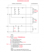
This would end up being wired like the Joe Rasmussen Elsinore speaker. You can ignore the impedance correction there. It is a simple coil on the basses and second order tweeter with Fs correction.
I impedance corrected a couple of basses to make things simple, and always a good idea with series filters anyway.
As noted, this capacitor circuit is NOT bafflestep. It transitions twin fullrangers to a single fullranger at mid frequencies with some changes to power response and phase, which ends up around 90 degrees between the two units.
Frequency response on axis is unchanged from a single driver. The top dotted line is the overlapped responses of the individual drivers without the capacitor. The bottom dotted line is the impedance without the capacitor.
Personally, I wouldn't bother with the capacitor, preferring MTM or MMT in principle.
To answer the original cabinet question, I don't see any problem with twin drivers series wired in a common closed enclosure. But remember that each driver only sees half the common enclosure volume. They are working together at low frequencies, which is where you would expect any unwanted interaction.
The extra fullranger employed as a reflex bass must be giving the full 6dB bafflestep that you get with a 2.5 way. I suppose in an ideal world you would also employ twin series-wired units here.
This would end up being wired like the Joe Rasmussen Elsinore speaker. You can ignore the impedance correction there. It is a simple coil on the basses and second order tweeter with Fs correction.
Attachments
Last edited:
Just so. As I noted above, it's generally used (when it is used, which isn't often) for the purposes of low-passing one unit to reduce the phase related destructive interference in the midband and HF, although it won't serve for addressing step loss, which many (not all) users of wideband drivers aren't too bothered about anyway for one reason or another, good or bad. 😉 You'll often find it lurking in that region though since if you're going to do it, you might as well do it relatively low down. If you want a full LP on one then you'd need to do something like Allen shows, albeit I suspect many wouldn't due to the additional components, which is something many wideband fans seem to be allergic to.
Elsinore's HP is a notched 1st order rather than a 2nd order IIRC, not that that matters.
Elsinore's HP is a notched 1st order rather than a 2nd order IIRC, not that that matters.
Yes, and it's an interesting one. What you seem to get is not only the extra bass potential and the single driver on higher frequencies, but it allows you to do independent bafflestep. ygg-it seems to be doing 3.5dB BSC rather than 6dB if I'm not reading it wrong.It transitions twin fullrangers to a single fullranger at mid frequencies with some changes to power response and phase
So it seems ygg-it has made solid choices.
- Home
- Loudspeakers
- Full Range
- Help me to understand this Series configuration