I just put together the circuit from the MAX629 data sheet and something isn't right. When I connect the power source the 629 gets hot right away and there is only the 3.7v input voltage on the output, not the 18v I was shooting for. I removed all the pieces on the board one by one until I narrowed it down to the inductor. As soon as I remove it the chip doesn't get hot anymore. I've spent hours going over my layout and I don't see anything wrong.:frown:
http://datasheets.maxim-ic.com/en/ds/MAX629.pdf
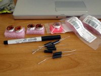
Pics of the board layout. The component labeled "30v 1A" is a Schottky diode with the cathode on the right. The input voltage is applied across the 100uf cap, and the output is across the 22uf.
http://datasheets.maxim-ic.com/en/ds/MAX629.pdf
Pics of the board layout. The component labeled "30v 1A" is a Schottky diode with the cathode on the right. The input voltage is applied across the 100uf cap, and the output is across the 22uf.
An externally hosted image should be here but it was not working when we last tested it.
An externally hosted image should be here but it was not working when we last tested it.
Do you know the saturation current of the inductor?
BTW: There is a lot to improve in this PCB layout.
BTW: There is a lot to improve in this PCB layout.
Eva, thank you for gracing me with your presence.😀
The inductor (NR4018T470M) is rated at 420ma.
http://www.rm-components.de/rm/PDF/praesentationen/NR.pdf
I have no doubt the board/layout can be improved, along with my knowledge of these things. I would compare my attempt here to that of a bicycle mechanic trying to build a rocket ship(a tiny rocket ship).😱
When you were testing was there any load on the output? Boost converters should always have a minimum load on their output. Try using a 20k resistor (or slightly lower) as a load.
Your layout connections are correct, but as Eva said in a reasonably nice way, the layout is far from optimal.
I would suggest reducing the inductor value a bit and choosing one with a bit higher current rating. Check out the evaluation board data sheet to see the recommended layout.
Your layout connections are correct, but as Eva said in a reasonably nice way, the layout is far from optimal.
I would suggest reducing the inductor value a bit and choosing one with a bit higher current rating. Check out the evaluation board data sheet to see the recommended layout.
I'm getting 7.5v on the output without any changes. It was 3.7 when I checked before.
Anyways, I put a 432r resistor on the output and the voltage drops to 6.5v and the chip still bakes. I tried a 10uH inductor, a bit low I think but it's the only other value I have unless I try putting some in series. With the 10uH I get the same voltage, but it takes a few seconds longer for the chip to heat up.
I think I will scratch this board and layout and try again. This time I am going to use the other side of the PCB as a ground plane and via and the ground points to it instead of daisy chaining them. Hopefully this helps. If not, I'm going to move on to a TPS61040.
Scratching the entire prototype without finding the problem is not the right way of doing things. Get an oscilloscope and investigate what's actually happening with the IC... The switching waveforms will provide a lot of information, you can even put a small shunt in series with the inductor in order to get current waveforms.
If the IC is overheating, that's probably because an unexpectedly high current is flowing somewhere (antd it's very likely to be through the inductor).
Hint: Try connecting ISET pin (5) to GND to reduce the internal current limit of the IC. Your inductor is very likely to be saturating despite the current rating, which is usually a thermal limit and sometimes is well above the saturation point.
Thanks for the help and suggestions Eva. Perhaps I do give up to easily(major personal flaw).
I really do need to purchase an oscilloscope. Whenever I have the money it always ends up down at the bottom of my list of things to buy. I always tell myself I don't do enough of this stuff to warrant the purchase of one.
I will try connecting ISET to ground, and if that helps or delays the heat-up I will go ahead and order higher current inductors.
It's really a pain having to order parts through the mail and paying $10 s+h for a $1 part.
Anonymous - I have a couple spare inductors I could send you that have a much more than adequate current rating for your project. They won't exactly fit on your board but they would be good to experiment with.
I've got some toroids and wirewounds in 33, 39, 47, 56uH values. Current ratings are easily above an amp.
I've got some toroids and wirewounds in 33, 39, 47, 56uH values. Current ratings are easily above an amp.
Attachments
Thanks for the offer Brian. I don't want to take one of your inductors from you just for testing purposes, as I would still have to buy a surface mount version through the mail if it worked.
Will an air-core suffice for testing? I don't have an inductance meter but I'm sure I can easily get in the 20-50uH range using an online air-core calculator based on wire gauge.
Will an air-core suffice for testing? I don't have an inductance meter but I'm sure I can easily get in the 20-50uH range using an online air-core calculator based on wire gauge.
Take it from me? They're just sitting around in a box doing nothing! It's a lot cheaper to test with these, figure out which one works best, then buy ones you know will work. I'll drop a few of the axial ones in an envelope and send them your way. An air core inductor would work, but will probably be bigger than any of the ones in the photo.
How do 27, 33, and 39uH sound? I would send the toroids but they would be way overkill for you application and are quite a bit heavier.
How do 27, 33, and 39uH sound? I would send the toroids but they would be way overkill for you application and are quite a bit heavier.
Brian, I would have said ok go ahead and send them had I read this post 10 minutes earlier. The lovely USPS man just delivered two AMP32 kits fresh from Sweden.
Now I have 8 10uH inductors to series/parralel as I see fit.😀
Now I have 8 10uH inductors to series/parralel as I see fit.😀
If you want to sacrifice a toroid and have enough wire, wind 2-3 layers on one of those cores. That should get you in the neighborhood of 30-40uH.
No stinkin' toroid winding here Brian. They are the AMP32 kits, not AMP3. The AMP32 comes with pre-wound high current SMD inductors.
Anyways, I don't think any inductor is going to help me here. I just tried 20uH and 40uH and the chip outputs the same voltage and still gets hot. I'm gonna go ahead and etch the new layout with all new components. If I still have the same problem, well then I'm not sure what the next step will be.
Anyways, I don't think any inductor is going to help me here. I just tried 20uH and 40uH and the chip outputs the same voltage and still gets hot. I'm gonna go ahead and etch the new layout with all new components. If I still have the same problem, well then I'm not sure what the next step will be.
theAnonymous1 said:They are the AMP32 kits, not AMP3. The AMP32 comes with pre-wound high current SMD inductors.
That makes it even easier for you!
Have you been testing with the same chip the whole time? It could be that the chip was damaged when initially powered it up.
Yeah I'm thinking it has to be the chip. I've tried changing every component on the board except the IC and nothing happens. I have tried various values for the voltage set resistors and the chip won't output any more than 8v. If I lower the voltage output to about 5v the chip doesn't get hot, but that isn't much of a help.
After all this soldering/de-soldering my board is starting to look like a peice of burnt toast. I think I have a better layout this time, so I will just etch a new board and use a fresh IC. I will try the new board with the 20uH large inductor setup to start.
After all this soldering/de-soldering my board is starting to look like a peice of burnt toast. I think I have a better layout this time, so I will just etch a new board and use a fresh IC. I will try the new board with the 20uH large inductor setup to start.
Success!!!!!!
I made a new board and it worked the first time I powered it up. I don't have the slightest clue why the first one didn't work. I didn't do anything that would have killed the chip. Maybe it likes this layout better, I don't know.
I was aiming for 18v and I get 17.98v with no load and 17.99v with a 3k resistor as a load.😀
Thank you guys for putting up with my amateur insecurities and lack of knowledge.
Here are some pics.....
http://i19.tinypic.com/4byy7ma.jpg
http://i19.tinypic.com/2j0zcqs.jpg
- Status
- Not open for further replies.
- Home
- Amplifiers
- Power Supplies
- Help: MAX629 DC-DC converter