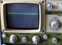
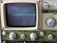
So I've done some measurements of my prototype board LM317 reg circuit. There was what appeared to be wide band noise on the output of about 2mV p2p.
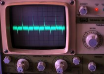
Stepping through the timebase settings and settling on 0.5uS/div it would appear that there is 4mV p2p at about 1.6Mhz on the output (same on the input to the reg).
I tried putting a 100nf polyprop cap across the output but it made no difference at all.
If I disconnect the scope probes from the circuit completely and leave them floating the 1.6 Mhz waveform is still there, at slightly reduced amplitude.
If I measure the circuit with transformer completely disconnected then there is a barely perceptible waveform, probably about 0.3mv p2p. Hook up just one side of the transformer winding and the waveform returns, pretty much identical to if both sides of the secondary are connected.
Last I tried just putting the scope probe across the 100nF cap, the 1.6Mhz goes away but there is still noise (probably much higher frequency). the really odd thing though is that rotating the scope probe 90 degrees (it is just being held by hand in the air with the cap on the end) the noise virtually goes away.
I don't know whether I'm just picking up airborne noise, power-line noise or both, and whether or not my rather dubious breadboard realisation (no component leads trimmed) is just acting as a big antenna.
anyway here are some pics.
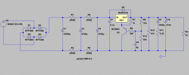
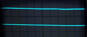
all measurements shown at 2mV / div and 0.5 uS/div.
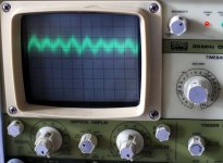
1st was taken using a 10V modem transformer (putting out around 12V ac as not heavily loaded) input to the reg 11.3 V reg output 7.5V
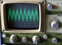
2nd was taken using a 15V transformer (putting out around 20V ac) input to the reg 19V out 7.5V
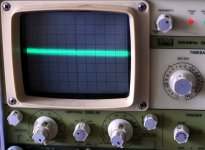
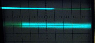
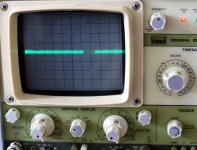
3rd pic is with the scope probes floating (just sitting on the floor not connected to anything.
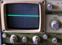
4th pic is with 100nF cap across the scope probe (nothing else).
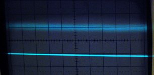
5th pic is with 100nF cap across the scope probe with the probe rotated through 90 degrees (axially).
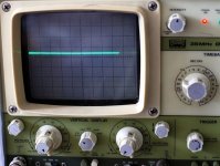
6th pic is what is present if connected to the PS output with the transformer disconnected.
7th pic is the schematic.
Any help with interpreting this will be greatly appreciated! I'm relatively new to using a scope and could well be doing something stupid, or there may be something wrong with it (as it was an as is second hand one).
More (earlier) measurements can be found on my blog entry http://www.diyaudio.com/forums/blogs/wintermute/574-yarps-finally-some-progress.html
Tony.
Stepping through the timebase settings and settling on 0.5uS/div it would appear that there is 4mV p2p at about 1.6Mhz on the output (same on the input to the reg).
I tried putting a 100nf polyprop cap across the output but it made no difference at all.
If I disconnect the scope probes from the circuit completely and leave them floating the 1.6 Mhz waveform is still there, at slightly reduced amplitude.
If I measure the circuit with transformer completely disconnected then there is a barely perceptible waveform, probably about 0.3mv p2p. Hook up just one side of the transformer winding and the waveform returns, pretty much identical to if both sides of the secondary are connected.
Last I tried just putting the scope probe across the 100nF cap, the 1.6Mhz goes away but there is still noise (probably much higher frequency). the really odd thing though is that rotating the scope probe 90 degrees (it is just being held by hand in the air with the cap on the end) the noise virtually goes away.
I don't know whether I'm just picking up airborne noise, power-line noise or both, and whether or not my rather dubious breadboard realisation (no component leads trimmed) is just acting as a big antenna.
anyway here are some pics.
all measurements shown at 2mV / div and 0.5 uS/div.
1st was taken using a 10V modem transformer (putting out around 12V ac as not heavily loaded) input to the reg 11.3 V reg output 7.5V
2nd was taken using a 15V transformer (putting out around 20V ac) input to the reg 19V out 7.5V
3rd pic is with the scope probes floating (just sitting on the floor not connected to anything.
4th pic is with 100nF cap across the scope probe (nothing else).
5th pic is with 100nF cap across the scope probe with the probe rotated through 90 degrees (axially).
6th pic is what is present if connected to the PS output with the transformer disconnected.
7th pic is the schematic.
Any help with interpreting this will be greatly appreciated! I'm relatively new to using a scope and could well be doing something stupid, or there may be something wrong with it (as it was an as is second hand one).
More (earlier) measurements can be found on my blog entry http://www.diyaudio.com/forums/blogs/wintermute/574-yarps-finally-some-progress.html
Tony.
Attachments

Welcome to the world of real testing 🙂
Are you using proper probes ?
First with scope probes shorted (tip to ground lead) and the vertical sensitivity set high check that the trace is pin sharp. Keeping the probe shorted touch the tip to the outer ground on the scope BNC input socket. The trace should still be noise free and sharp.
Next connect the still shorted probe to the ground on your working circuit... does the trace thicken and show noise ? If so you have a connection/ground problem.
Any HF picked up by the "open" probe could be anything from radiated noise from a SMPS in a TV/PC/DVD etc etc to genuine RF froma transmitter if one is nearby. the scope is showing what is there.
Edit... some real world testing on a reg. Read the whole thread, but scope piccys started here,
http://www.diyaudio.com/forums/powe...egulator-between-jung-flea-3.html#post1574217
Last edited:
Thanks Mooly 🙂 It looks like maybe part of the problem is with the probes... One is a bwd P32 probe (switchable 1X 10X) which was brand new and came with the scope (though having just done a google search it could be a cheap knockoff). One thing I just read is that it is only rated up to 12Mhz in the 1X position, but I don't think this is where my problem is coming from.
The other is a 60 mHz 1X /10X probe I got from jaycar a few years ago to use with my soundcard preamp with pc based scope software. So both are real probes but not necessarily great quality ones.
I get a fairly sharp trace even at 0.2uS/div 2mS/div with the probe tip shorted to the earth connector, however I get the same phenomenon as with the cap, ie changing the position of the probe in the air changes the sharpness of the trace.
Touching the still earthed probe tip to the bnc socket (can only do it with one as the other is completely insulated) can display a clean trace or a very noisy one which appears to be modulating in time with voices playing on the TV!
When I the touch it to the ground on the PS it is a very noisy trace same sort as above with modulation in time with voices on the TV (can't turn it off at the moment my Daughter is watching postman pat 😉 ) I did turn it, the amp and the HT PC off when I did the earlier measurements though and it didn't seem to make any difference then.
Note that the ground in the schematic is not really a ground. I'm using an old model train transformer, I've tried both the AC and the voltage controlled DC output of it but I don't have a connection to earth per say, so the ground is floating in the PS.
Attached some more pics.
1st is showing both probes shorted oriented to give the sharpest trace (note that even with the scope switch set to short it is pretty much the same as this).
2nd pic shows the same as above but the second probe rotated on its axis. Both pics were 2mV/div 0.2uS/div.
The next two pics were taken at 1ms/div and 5mV/div.
3rd pic is with the probe still shorted touched to the BNC on the scope, note that in a different orientation it gives a completely clear a trace.
4th pic is with the probe still shorted touched to the PS ground point. In this case the orientation of the probe didn't seem to make much difference at all.
So it would seem that there are perhaps multiple issues going on 🙁
I just tried the other transformer I have (a modem transformer) instead of the train transformer, the bulk of the noise was less than 4mV p2p, so quite a bit lower than with the train transformer. The train transformer provides current limiting by passing the current through incandescant bulbs so whether that would cause any additional noise I'm uncertain.
Tony.
Attachments
A lot could be happening for sure.
When a probe is switched to "divide by 10" the scope it puts a 9meg resistor in series with the signal. Its not quite that simple as the probe then has o be compensated so that it accurately displays a squarewave without over or undershoot. Im mentioning that because it means the lead and part of the probe is at high impedance and prone to stray pickup. In "time 1" position it is a direct connection to the scope.
http://scope-probe-schematic.blogspot.com/
The modulation looking like audio suggests stray pickup from something... could the lead be acting as an antenna and picking up AM broadcast ?
The fact the scope can give a clean trace suggests there isn't a problem there.
In a domestic setting with all the "noise" and so on around you may struggle to get a clean trace... its very hard to say and diagnose without being there and trying stuff.
Your 4th picture looks pretty typical for just connecting a scope to the ground on a circuit.
I have seen similar with the scope connected across the speakers in a normal set up yet with all the equipment totally switched off... anything and everything picks up noise of various sorts.
Hi Mooly, I just rechecked the AM dial on a radio, and 1.6Mhz is most certainly within the ballpark (it goes up to 1.7Mhz) On the previous occasion I measured it appeared to be a 1.1Mhz carrier, it is definitely amplitude modulated as well. I'd previously discounted it (as being AM radio) because I'd misread the dial on the radio, didn't see the X10 and thought it only went to 170Khz.
Also my chip amp will act as a radio if I only insert the rca lead half way (ie only the tip but not the shield) so there could well be some strong AM signals around my home.
I'll keep my eye out for a 1:1 tek probe though I suspect it will cost me more than the scope did 😉
The other thing that is a bit odd is that the noise was much lower the first day I did measurements, however I know that AM signal strength varies a lot with atmospheric conditions so could just be the signals were higher today.
Looks like my thoughts of being able to measure small changes due to differences in IN-OUT voltage differential and higher ripple on the input are not going to be possible 🙁 not without building myself a Faraday cage and super mains filter anyway 😉
Tony.
Hi Sy no it wasn't (I'd never listen to AM either!!) 😉
The TV was on, but it was running off the HT PC which has a digital tuner card in it. I have no idea what that runs at, but in my first lot of tests, disconnecting the TV antenna from the wall socket made a BIG difference to the noise levels.
Just to make things more weird, I just did another measurement with the modem transformer, and the TV on but not playing anything. 5mV/div 1mS/div (on the second channel of the scope, and yes I did compare both before and they had the same results) and now it looks very clean in comparison except for a few points where there are some spikes... so whatever is causing the noise seems to be variable and intermittent.
The only other thing I did was adjust the probe in the 10X position, it had quite a bit of overshoot on the test squarewave built into the scope, whether that could have been causing problems in the 1X position though I don't know, but Mooly's comment about picking up stuff made me think it was worth a shot.
edit: oh and in the 2mV/division mode it looks a LOT nastier (much less stable and heaps more noise) I'm wondering if that may be causing some issues in itself, perhaps some problems with the extra gain. This last measurement was done with the TV arial connected, but the scope is plugged into a socket on the other side of the room (which it was for all of todays measurements)...
Tony.
Attachments

Last edited:
So I decided to try again today. I unplugged everything from the power except the scope and the transformer, I got good results!
First pic is the input to the reg 2mv/div 10ms/div you can see from this that the CRCRC is doing a good job of cleaning up the DC!
Second pic is the output of the reg whilst drawing around 300mA (1st pic same load).
Third pic is with the scope switched to shorted input to show the minimum thickness trace I can get on this scope.
So overall I'm quite happy with that 🙂
Interestingly I just did some more measurements and the interference has come back. first measurements were this morning, so could be something that someone turns on in the afternoon (not in my unit).
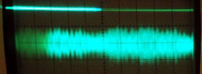
I just measured the output of the reg with it feeding the square wave generator I just created, it seems it doesn't cope so well with the square wave generators power demands... 4th pic attached 50uS/div 2mV/div The square wave is around 9.2Khz.
Not sure if this is really a fair test though...
Tony.
First pic is the input to the reg 2mv/div 10ms/div you can see from this that the CRCRC is doing a good job of cleaning up the DC!
Second pic is the output of the reg whilst drawing around 300mA (1st pic same load).
Third pic is with the scope switched to shorted input to show the minimum thickness trace I can get on this scope.
So overall I'm quite happy with that 🙂
Interestingly I just did some more measurements and the interference has come back. first measurements were this morning, so could be something that someone turns on in the afternoon (not in my unit).
I just measured the output of the reg with it feeding the square wave generator I just created, it seems it doesn't cope so well with the square wave generators power demands... 4th pic attached 50uS/div 2mV/div The square wave is around 9.2Khz.
Not sure if this is really a fair test though...
Tony.
Attachments
Pleased you are figuring it out and getting better results.
Remember a regulator is very much like an amplifier and feedback network, The output of the reg is only correct and constant at one point... the point where the feedback and error correction is performed and its feedback return point. So on a three terminal reg the only meaningful test is with the scope on the reg ground and output pin. As soon as you move away from the reg (down wire and print) the output will not be as good due to resistive effects that develop unwanted volt drops etc. This is the problem with so called super regs that are hard wired onto a PCB. The reg itself may offer better performance than say a 7812 but once you feed it down a wire and so on the result at it's destination may be worse than a local 7812 right at the point where its needed.
Remember a regulator is very much like an amplifier and feedback network, The output of the reg is only correct and constant at one point... the point where the feedback and error correction is performed and its feedback return point. So on a three terminal reg the only meaningful test is with the scope on the reg ground and output pin. As soon as you move away from the reg (down wire and print) the output will not be as good due to resistive effects that develop unwanted volt drops etc. This is the problem with so called super regs that are hard wired onto a PCB. The reg itself may offer better performance than say a 7812 but once you feed it down a wire and so on the result at it's destination may be worse than a local 7812 right at the point where its needed.
You may also need to think about the 'scope ground.
If the 'scope is connected to mains ground using a standard 3 pin mains cable/ plug, all kinds of problems (simplest is a classic ground loop) can show up after connecting the probe ground clip in to a circuit.
I am NOT advocating the following as it is potentially unsafe, but in many instrumentation labs I have worked in there was a ground lift switch for the scope, opened up after the connections were made.
Plus suitable warnings, disclaimers and sirens going off!
Think safety first ....
An isolation transformer can also be used to good effect.
Last edited:
Thanks Mooly, I was near but not on the out pin, also since this is a breadboard circuit it is not optimally laid out with respect to the positioning of the feedback resistor (I plan to solder it direct to the reg pin. Also the ground and load pickup points are not optimally positioned either. Also I ran long (breadboard jumper) wires for power and earth for the square wave generator as I implemented in on the unused half of the breadboard, so that won't have helped either 😉
Cliff, yes there is definitely a potential problem with ground loops with my scope, but not in this particular case, as I'm using a two pin plug pack for the transformer at present. The final supply will have a three pin supply though but I will probably implement a ground loop breaker. I'd actually been wondering how people dealt with ground loop problems, I think I'll just rely on my earthloop breakers for now 🙂
Tony.
- Status
- Not open for further replies.
- Home
- Amplifiers
- Power Supplies
- help making sense of measurements