Hello
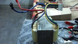
I got this transformer from an old ups, there are four wires on the primary side black, blue, green , yellow and two on the secondary red and blue. This transformer used to charge 12v 7.5ah battery also converts it back to 220V in backup mode.
Tried testing its output and got this
(Mains 220V)
Black to ground
Blue to mains-> 7.9v on secondary
Green->5.5v
Yellow->6.5v
Connecting Blue and Green to mains and it was a shot circuit, blown my fuse. I want to use this for making a decent power supply 12v+ output, is this possible?
I also saw this video https://www.youtube.com/watch?v=mc4GZM-kFUY&hd=1
The guy is using his ups transformer for generating hv to power cfl using tip122, i am not sure how to do this using my transformer.
I need to make use of this transformer somehow, otherwise its just eating dust at my home.
Attachments
Seems logical, they must be taps with ~50V between themConnecting Blue and Green to mains and it was a shot circuit, blown my fuse.
No, unless you resort to a voltage doubler, which will be messy and ineffective (and will turn an insufficient voltage into an excessive one)I want to use this for making a decent power supply 12v+ output, is this possible?
Using a big ugly 50Hz Xformer for that task is a complete waste of resources when a 50KHz one the size of your thumb could do exactly the same job, just more efficientlyI also saw this video https://www.youtube.com/watch?v=mc4GZM-kFUY&hd=1
The guy is using his ups transformer for generating hv to power cfl using tip122, i am not sure how to do this using my transformer.
insulate all the wire ends by fitting each into a receptacle of an insulated terminal strip.
The screw down will punch through the enamel insulation.
Measure the resistance of pairs of tappings to identify each winding. Label the windings.
Identify what you think are the primary wires.
Connect a mains lug to these.
Power up via Mains bulb tester. Does the bulb light up?
if yes then you have a wiring fault.
If no then proceed.
Now you can safely measure voltages at all the tappings.
- Status
- Not open for further replies.