I made home speaker towers using high end coils and caps and I have a problem with the high end ripping my face off. It sounds like horns, very squawky. It's horrible.
I have the Focal TLR tweeters, 6 ohms and I have joined them with the Focal Utopia 4W2, 4 ohms. I have them cross over at 3000 Hz, but, the program I used to figure out what coil and cap value to use, was set for a Butterworth crossover. I believe I should have used the Linkwitz-Riley 12db/oct... for a flat response. As I figured out, with the butterworth crossover, will give me a 3db gain at the crossover point. I have a feeling this is where it is ripping my face off... I think.
Any suggestions, if I were to raise the tweeter up in frequency, where should I set it up too, keeping the 4" at 3000 hz? Just remember I am trying to do as little value change as possible. The coils and caps were expensive!
I did use resistors and I can't tone it down just right... It just makes it quieter...
I understand different impedances at different frequencies and all the other jaz, so, please don't say negative things for my attempt. I need suggestions. Thanks
do you have any data on those drivers? I did a quick search on the tweeter and didn't turn up anything. striking out on the mids as well.
Without knowing what the sensitivity of each driver is and a frequency response curve (preferably on your actual baffle) it is very hard to say anything.
A text book crossover is not going to give you good results unless you have very flat drivers with constant impedance and a large overlap either side of the crossover frequency. (which is highly unlikely).
A lesson for future projects, make your initial crossover with relatively low cost parts, it is highly likely you will end up changing them!
Measurements at this point are your best bet. However if you can't and you haven't already done so, have a read of http://www.diyaudio.com/forums/mult...designing-crossovers-without-measurement.html
Tony.
Last edited:
Yeah, textbook crossovers are pretty much useless in practice. It sounds like several mistakes are piling up.
1) the TLR tweeter is roughly about 10db more efficient than the 4W2
2) the 4W2 is a midrange, not a woofer
3) it sounds like you didn't account for baffle loss, so add another 4-5db to the difference
It's not at all surprising that it's ripping your ears off.
I thing the best bet would be to add a woofer, and pad down the tweeter with an L-pad (not a resistor).
Designing crossovers is not trivial. You may want to pay someone to do if for you, or spend a few months learning. There isn't really an easy way out. You will need measurement equipment.
It's possible to do an exact simulation for a crossover design based on the FRD/ZMA's data. It doesn't mean you will be using the same components that you are using.
What components do you have?
For an approximate, read, a starting point design (below) crossover use for the tweeter a third order and for the mid a second order.
A 2R0 resistor is giving the approximate tweeter attenuation, use a variable L-pad for preliminary measurement* or adjust with different resistors. Yours will have to atten. maybe 3-6dBs more from using one driver only. Nnotice that you have a 4 ohm driver and this design is for a parallel 8 ohm, components should be similar not far away from a final design. 😀
* if you have a multimeter (VOM).
http://www.diyaudio.com/forums/multi-way/127183-focal-bookshelf-audiom-tlr-7w4411.html
Focal 4W2
Focal Audiom TLR freq
Another interesting 3-Way design, Andromeda MK-II pdf
Ok, so I did originally have my set up using cheaper coils and caps. The other drivers I have in the cabinet are set up with the suggested coils and cap values from Focal. This was years ago... I only went bigger and better because I was melting the caps and some of the coils were too small, especially for the subs... Where my problem is, back then, they designed it with the FA 110KX crossover in it. For the Tweeter and 4". This is where my problem is. Because the new coils and caps are that much better, they are much brighter and louder. If you saw the old crossover, it is pathetic. It was 12db/oct for the tweet and 6db/oct for the 4". But, for the coils there are no numbers and they are small. So, I some what guessed using a program...
I only have a sensitivity chart for the Audiom TLR tweets.
So, going back to the butterworth crossover, it will have a 3db peak at the crossover point. Now if I used the Linkwitz-Riley set up, their cut off for both speakers are further apart, yielding a flat crossover point when combined. So, if I were to keep the 4" at 3kHz, which would be -3db (butterworth), it might be 3,5kHz @ -6db for Linkwitz-Riley, so, where would I need the tweeter to cut off at to yield a flat response. 4.5kHz @ -6db for a Linkwitz-Riley? Does this make sense?
I am going off of a chart I googled. I cannot attach it. It is on Wikipedia: "Linkwitz-Riley filter". It has a chart on the right.
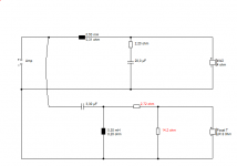
So ignore my last entry. For my tweeter, I have 6.2 uF cap and a .45mH coil, no resistors yet. For the 4" I have 9.3uF cap and a .3mH coil, no resistor yet. From my listening, it seems I have a peak around the 3kHz area. I am trying to match these speakers together.
I think you're way off the mark altogether here. Talk of Butterworth and Linkwitz-Riley is just not helpful either.
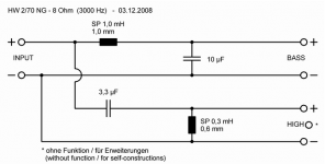
Here's an off-the-shelf 8 ohm 3kHz filter:
HW 2/70 NG - 8 Ohm
You seem to have a 4ohm reflex 4" driver (Qts=0.3?) and a 8 ohm tweeter. I'd guess you need a small box between 5-10 Litres. It won't be dissimilar to this Troels Gravesen project: Eekels' Mini
I just ran that 8 ohm Visaton filter past Visaton Boxsim with the 4 ohm W100S and it all worked quite well. The tweeter attenuator is the crucial adjust. You want to keep it around 6-9 ohms load to the filter.
The way the slopes worked, it seemed to be saying third order tweeter would be even better, which is what Troels did. But 1mH bafflestep coil on a 4 ohm bass is entirely reasonable.
Attachments

The first thing I'd do, given where you're at in the build, is find some halfway flat mic and run it into your sound card. Download the free Visual Analyser program. Now you have a spectrum analyzer.
Next, burn a CD with some wideband noise, maybe generate it with Audacity. Play the CD and use the spectrum analyzer to see what your response looks like. If the tweet is just hot, pad it down with an L-pad or resistors. Just do something, anything, to get it down to the level of the woof. (Visual Analyser can probably generate the noise in real time, depending on your setup. I just find having the CD is often easier because my source and measurement system are then entirely separate.)
Now, if the resulting response is reasonably flat, great. If it isn't, you'll have to modify the crossover. Before that, if you have a small hump or dip in the middle, try reversing the phase of the tweeter.
IMO, the last step of speaker design is always tweaking by ear, but test equipment is absolutely necessary to get the major bugs out.

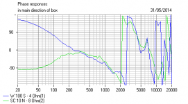
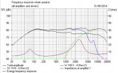
I always try to get a feel for a crossover and drivers with some rough and ready modelling. coryvirtue, your first effort is pretty disastrous, if you don't mind me saying so. You knew that. Here's something like what you are hearing now. 🙂
I modelled this as a 12cm wide standmounter cabinet which seemed to work. The HW 2/70 NG - 8 Ohm filter seemed to give something closer to a tolerable speaker and gives a point of departure for this project.
This is rough and ready, but what I'm getting here suggests a 1.5mH bafflestep coil might be better to get that midbass slope down. Or 1.2mH coil and a 10W 2.2R wirewound in the bass shunt arm. I think you'll need to experiment, because I can't read your Le woofer inductance which affects this.
Your tweeter is a high 95dB efficiency too, I used a 90dB jobbie. So the attenuator will need to do more too. A third order tweeter wasn't so nice on phase. Not that anybody, except me, is ever interested in THAT. 😀
Attachments

Just wanted to say thanks for all your information. It really helps me out. Can't wait to adjust it! My 5 way towers were a lot of work to do. (2) 15"'s per tower in a isobaric configuration. Should be really tight!
Are you kidding?!My 5 way towers were a lot of work to do. (2) 15"'s per tower in a isobaric configuration.
Is it a 2-Way or what... 😕
FRD/ZMA's data. 😉
Ha! I suppose that is good work, Inductor. But now we need a spec sheet or two that we can actually read, don't we? 😱
Can you dig those up? So far that woofer is looking a bit weird. Huge bump in the midrange due to the surround I suppose. The SPL Tools files lack phase as well. Not clear what baffle they were modelled on either. 😕
I think you're having a laugh! 😉
BTW, can everyone please explain what they mean, rather than post links and run away giggling. I know it's a BORE writing more than one line, but otherwise these threads go on forever.
Last edited:
The 4" driver is really a mid driver in a reflex would have a 1.6 L@76.6 Hz, and it shows a very different frequency curve (from what was expected). Now on a sealed for a 5 way that would be another game deserving attention (very different not only in the design but because of the crossover parameters if a passive is on the table, I have no idea (with secretive posters). Better for OP's (in general, NPI) to open their game from the start, so we can understand what they are after...
PS. the 3. order for the tweeter gives very nice results (phase) easy to simulate and manipulate for a smooth HF output as predicted but with different value components, very nice project. note: if you are using the phase of the preexistent drivers, turn them off and on after you input the new drivers FRD/ZMA's from post#14. Give new data for the enclosure (above), reflex or sealed, in the 4" Focal parameters. 😀
PS. the 3. order for the tweeter gives very nice results (phase) easy to simulate and manipulate for a smooth HF output as predicted but with different value components, very nice project. note: if you are using the phase of the preexistent drivers, turn them off and on after you input the new drivers FRD/ZMA's from post#14. Give new data for the enclosure (above), reflex or sealed, in the 4" Focal parameters. 😀
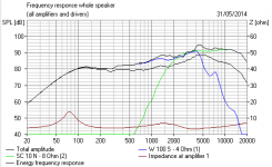
Yup, I agree Inductor. That woofer is unusual. It has a surround peak at 2kHz which makes it bend down rapidly after filtering. That must be why the Qms is a very high 8.99. I guess it's got a fairly rigid surround, as you might expect with a midrange optimised driver.
I don't really know what I'm doing with the levels here, because there's a mix of SPL units in the specs and I'm too tired to do the conversion. 1W/1m and 2.83V.
Anyway, here's the surprise. The Focal woofer actually seems to need a 4 ohm filter after all. That is what I'm getting now. But I'd like someone else to look at it, particularly since I don't know what baffle the files were measured on either. The bass response is a bit odd, there isn't much of it!
Attachments
Last edited:
You can't do that.It is a 5 way set up. I am just having problems with the highs. The 4" and tweeter.
If a passive system (all) the components will have to be taken into account.
Unless you are doing an active system (amp) for the HF with the 4" mid + tweeter only. 🙂
- Status
- Not open for further replies.
- Home
- Loudspeakers
- Multi-Way
- help! I need passive crossover point suggestions