Hi everyone!
I am a new member so thanks everyone for the very useful infos I already found here, I hope to write in the right section and that I will understand your answers 🙂
I am a newbie, and this is my first build, I did some simple repair to my tape recorders (mostly mechanical and recap) and I'm studying the basic of electronics, but I am still at the beginning. Anyway I can solder reasonably well, can read simple schematics, and have some basic tools (including some components, breadboard and multimeter), so I feel ready (maybe 🙂 ) for my first project.
I am a musician and "sound artist" and I need a simple mixer for live reproduction of some field recordings and electronic sounds in places with no PA and no electricity (I will use battery T-amps and small passive speakers), so I am planning to build a virtual earth mixer to my specific needs:
- portable: maybe in a guitar pedal enclosure;
- battery powered: with two 9v batteries or two 12v Li-ion battery packs;
- 3 or maybe 4 stereo inputs: I have two digital players (with line out) and some cassette recorders, probably unity gain will be ok;
- two stereo outputs: I need to send the stereo tracks to one stereo output or the other or both;
- no need for balancing/panning, master pot or eq;
- double gang pots for each stereo track;
- I may also need mute switches but I'll about it later.
I found some schematics here:
Simple Mixer Schematics
also discussed here in the past
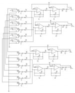
I removed balance and master pots and made a drawing with scheme-it, I hope it's clear, at least to understand the idea.
Now with the questions:
Is it right? I am thinking to use NE5534, are the components values ok for those op amps?
In the sketch I just connected the input jacks to two identical mixers, is it ok or some kind of buffer is needed to split the signal?
Thanks in advance for any help!
I am a new member so thanks everyone for the very useful infos I already found here, I hope to write in the right section and that I will understand your answers 🙂
I am a newbie, and this is my first build, I did some simple repair to my tape recorders (mostly mechanical and recap) and I'm studying the basic of electronics, but I am still at the beginning. Anyway I can solder reasonably well, can read simple schematics, and have some basic tools (including some components, breadboard and multimeter), so I feel ready (maybe 🙂 ) for my first project.
I am a musician and "sound artist" and I need a simple mixer for live reproduction of some field recordings and electronic sounds in places with no PA and no electricity (I will use battery T-amps and small passive speakers), so I am planning to build a virtual earth mixer to my specific needs:
- portable: maybe in a guitar pedal enclosure;
- battery powered: with two 9v batteries or two 12v Li-ion battery packs;
- 3 or maybe 4 stereo inputs: I have two digital players (with line out) and some cassette recorders, probably unity gain will be ok;
- two stereo outputs: I need to send the stereo tracks to one stereo output or the other or both;
- no need for balancing/panning, master pot or eq;
- double gang pots for each stereo track;
- I may also need mute switches but I'll about it later.
I found some schematics here:
Simple Mixer Schematics
also discussed here in the past
I removed balance and master pots and made a drawing with scheme-it, I hope it's clear, at least to understand the idea.
Now with the questions:
Is it right? I am thinking to use NE5534, are the components values ok for those op amps?
In the sketch I just connected the input jacks to two identical mixers, is it ok or some kind of buffer is needed to split the signal?
Thanks in advance for any help!
Attachments
Last edited:
How long is your output cable? 24 ga twisted pair is about 30 pf/foot, RCA coax cable is about 100 pf/foot. More than about 6' your highs may be filtered out by the cable using 5534 as line driver. More than 6' Peavey uses NJM4580 for line drive which is only dual per package. Or surface mount 4565.
NE5534 uses more electricity than competitive quiet op amps like 33079. You do have to to provide .1 uf ceramic cap within an inch of package with high slew rate 33079. If you are in a small country with limited supply a 4558 would be okay at these low gains. 50* gain 4558 is hissy. I have to say with 9 v batteries running $9 for two I would not be using them.
I think you need to provide resistors to plus inputs of op amps to power supply center to establish gain. Half value of feedback resistor would give you 2* gain. With 9 v supplies your maximum input signal could be ~6 vac.
1 megohm to center from your pot wipers could reduce huge pops when the wipers lose contact. If you are within 20 miles of an AM radio station or a business/police/fire band radio you may want to put 39 to 68 pf between center and ring of input jacks. Also use a steel case connected to power supply center. 5 to 10 turn coils series the outputs could prevent RF from coming in that way.
Last edited:
The input impedance is a little on the low side at 5k.
'5534s are not a great choice for battery power. Many newer designs drink 1/10 the power or less, at only a nominal sacrifice in SQ.
If it's only the channel assignment that differs between the stereo output pairs, switches would be both be more reliable, and a lot easier to manage (without 'cockpit error') in use. It would drive me nuts, trying to keep two gain pots matched, under performance conditions.
But that's probably just me 😱.
You may also want to add 'bleeder' resistors on the 'outside' of coupling capacitors, for example C11, C12, C17, and C18.
Cheers
Last edited:
Hi! Thanks for answering, I try to reply to both, and later I'll correct the schematic according to your suggestions.
@indianajo
The output cable will be ideally around 50cm, so probably no high frequency loss on that side.
I had a look at the 33079 op amps and they seem to be a good improvement for powering but in a quick search I found the SMT version only. I would prefer a through hole component with socket for easy replacement in case I want to compare similar op amps.
In general I would like the mixer to sound very good, any other suggestion? TL072/082 or TL074/84? (I already have a couple TL072 here)
As you suggest I will not use 9v batteries, I'll use two 3000mA 12v Li-ion battery packs (I already have them) do you think the op-amps power consumption will be still an issue?
"I think you need to provide resistors to plus inputs of op amps to power supply center to establish gain. Half value of feedback resistor would give you 2* gain." Sorry I'm not sure I understand: do you think there will be so much signal loss in the circuit to need 2* gain?
I will put resistors between wiper to ground and I will use TRS instead of TS to put capacitors between ring and sleeve, thanks for the suggestion (hope I got it right).
@Rick PA Stadel
I'll try to find something to read about the impedance issue you're talking of, would you suggest different resistor values for R7 to R12 and R29 to R34 or 20k pots instead of 10k?
Any suggestion from you too for better op amps with minimum sound quality loss?
I will also add resistors between caps and outs, how do I calculate the resistor values to use? (or if you suggest the values I promise I will study for the next time 🙂 )
I understand your doubts about switch/pots but I'm afraid I cannot sacrifice the individual pots for each stereo channel (I will use double gang pots at least 🙂 ), as usually I am constantly fading in and out the tracks. I will place on/off switches somewhere later, still have to decide if after or before splitting signal.
Anyway thanks a lot, I already have too much stuff to study
Have a great day!
Glauco
With a resistor value of zero from + input to power supply center, your original design has a gain of rf/ri of infinity. If your input has >1 vac you run the risk of violating the differential input voltage spec and blowing the base to emitter junctions of the input transistors of your op amps."I think you need to provide resistors to plus inputs of op amps to power supply center to establish gain. Half value of feedback resistor would give you 2* gain." Sorry I'm not sure I understand: do you think there will be so much signal loss in the circuit to need 2* gain?
If your gain is <5 you had best check that your op amps are unity gain compensated. TL072/74 is much noisier than 33079 or 33078, but at gain 1 you may not hear it. If you have a gain of 1 I don't quite understand why you want an input op amp at all. The output op amp can drive your cable capacitance.
Bleeder resistors outside your coupling capacitors can be 1 megohm or 470 kohm to power supply center, just enough to dissipate static charge.
33078 is a dual in line version of 33079 with two in a package. Equivalent low cost low noise amps are NJM2068. I've never worried about low power, so I suggest you have your supplier search for low power dil op amps for you, then read datasheets to evaluate what he has in stock. Current noise and voltage noise as low as 33078 are desirable, but not crucial at gain 1. Unity gain stability is.
Current noise & voltage noise quoted in square root of hz can be compared to microvolt or microamp noise specs of other amps by multiplying by sqrt(20000 hz-40 hz) or 141. Noise specs tested at different noise source impedances are not directly comparable.
If you use TRS input jacks and put capacitors between R&S, and connect the input to tip, you are subjecting your op amps to all the RF that the world and your input cables can transmit to you. RF filter capacitors need to be between + & - inputs of the op amp. Locating RF filter capacitors at the op amp makes little antennas out of the wires over from the jacks. Wavelength of a cell phone frequency is about an inch.
Last edited:
Thanks for the reply and for the help @indianajo, as I am a noob I can partially understand what you say, but I will take it for granted and hopefully I'll understand more in the future. For the moment I'll be happy to have the right schematic to order components and start to breadboard the circuit.
33078 is available so I will order that.
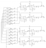
I updated the schematic drawing to your and Rick's suggestions, but I'm not sure to have done it right and I miss some values.
- Added 1M resistors to pot wipers, and 1M bleeder resistors between caps and outs;
- Added resistors to + input of op amps, but I don't know which values to use;
- Changed pots from 10k to 20k;
- Also added 39p caps between + and - inputs of op amps as suggested.
You'll find the drawing in attachment, so you can tell me if I understood your advices and placed components and connections correctly.
Thanks again!
33078 is available so I will order that.
I updated the schematic drawing to your and Rick's suggestions, but I'm not sure to have done it right and I miss some values.
- Added 1M resistors to pot wipers, and 1M bleeder resistors between caps and outs;
- Added resistors to + input of op amps, but I don't know which values to use;
- Changed pots from 10k to 20k;
- Also added 39p caps between + and - inputs of op amps as suggested.
You'll find the drawing in attachment, so you can tell me if I understood your advices and placed components and connections correctly.
Thanks again!
Attachments
R22 & R23 are picked to set the gain of the amp. What gain to you want? I can't read the R numbers or the resistor sizes. If your output to minus input resistor is 18k, then for gain 1 the plus input to power supply center resistor should be 18k.
Putting 39 pf between + and - inputs of op amp leaves the wire from the input jack to the op amp to transmit RF. At cell phone frequencies the length of these antennas at 4 cm is a half wavelength. You need to put the RF kill capacitors on the jack itself. Between tip & shaft if using TRS jacks.
Putting 39 pf between + and - inputs of op amp leaves the wire from the input jack to the op amp to transmit RF. At cell phone frequencies the length of these antennas at 4 cm is a half wavelength. You need to put the RF kill capacitors on the jack itself. Between tip & shaft if using TRS jacks.
Ok for the RF kill capacitors, now I understand, sorry for being so slow 😀
I omitted the R22, R23 etc values because I don't know how to calculate the values, in the first reply you suggested 2 gain so I will trust your advice.
I omitted the R22, R23 etc values because I don't know how to calculate the values, in the first reply you suggested 2 gain so I will trust your advice.
Sorry indianajo, but the '+' inputs on his op-amps are at ground because he's using them in inverting mode. The inputs to the '-' input are currents; the amp then matches that current (equal but opposite polarity) by slewing the output 'til the feedback resistor conducts the same current. Two successive inverters return the output to the same phase as the input -- not everyone cares, but some do.
I've read so many sharp posts of yours .. maybe this crossed your field of view just too close to the end of a long, long day of yours .. ? 😉
The original circuit had shortcomings, but would have worked -- as long as the op-amps were unity-gain stable. The revisions will take a little more study, on my behalf at least.
Cheers
edit: I'll keep putting them in here as long as it allows: The 'bleeder' resistors are shunts to ground. They can't be in series with the output coupling cap. Their job is to maintain the jack signal pin at ground, even with nothing connected. 47k to 220k would be a better choice of value.
2: R45 through R56 are misplaced: They belong from ground to wiper. The location in post 6 will defeat the gain pot altogether -- maximum attenuation will be 0,17dB.
3: C26, C13, C17 and C29 are not needed -- the RF comes from outside; if it doesn't get past the 1st stage, it won't appear at the 2nd. If you keep the resistors '+' to ground, the capacitors shunting the inputs affect stability; not all op-amps will tolerate them.
Last edited:
Op do you really need 2 separate mixes as your input circuitry puts quite a load on your equipment .
Last edited:
epicyclic thanks for the interest,
I need to be able to send each stereo track to output 1 or output 2 or both, and to control the volume to each output separately.
In my Soundcraft mixer I use fader for one output and pre-fader aux 1 and 2 for the other output.
Having two separate mixer sections was the simplest way for a noob like me to think it starting from the schematic I found.
There are battery powered mixers with one stereo output available, another solution would be to buy two of them and just split the input signal with Y cables, but I will spend more money, probably the mixers will not sound good (as they are really cheap), they will take more space, and will be less comfortable to play with.
That's why I thought to try the DIY route, as the starting schematic seemed not so complicated, and I am always willing to learn.
I can also consider the idea to have it built by someone professional or at least more experienced than me. I will trust your advice as expert diyers on this too, if you think that the project is too advanced or problematic for a beginner.
Sorry indianajo, but the '+' inputs on his op-amps are at ground because he's using them in inverting mode. The inputs to the '-' input are currents; the amp then matches that current (equal but opposite polarity) by slewing the output 'til the feedback resistor conducts the same current. Two successive inverters return the output to the same phase as the input -- not everyone cares, but some do.
I've read so many sharp posts of yours .. maybe this crossed your field of view just too close to the end of a long, long day of yours .. ? 😉
The original circuit had shortcomings, but would have worked -- as long as the op-amps were unity-gain stable. The revisions will take a little more study, on my behalf at least.
Cheers
edit: I'll keep putting them in here as long as it allows: The 'bleeder' resistors are shunts to ground. They can't be in series with the output coupling cap. Their job is to maintain the jack signal pin at ground, even with nothing connected. 47k to 220k would be a better choice of value.
2: R45 through R56 are misplaced: They belong from ground to wiper. The location in post 6 will defeat the gain pot altogether -- maximum attenuation will be 0,17dB.
3: C26, C13, C17 and C29 are not needed -- the RF comes from outside; if it doesn't get past the 1st stage, it won't appear at the 2nd. If you keep the resistors '+' to ground, the capacitors shunting the inputs affect stability; not all op-amps will tolerate them.
Thanks Rick for the reply:
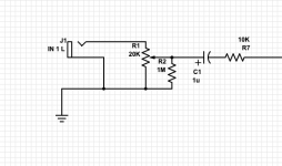
So should I connect the bleeder resistors like this (picture)?
Sorry I was a little confused from all the informations 🙂 is the wiper resistor connection correct now (other picture)?
As indianajo suggested I'll remove caps from + - op amp inputs and just put them in the input jacks.
I will also remove +input to ground resistors, right?
Attachments

Both of the schematic bits in post 12 are spot on! 😀
The resistors from '+' to ground on the op-amp inputs can actually serve a purpose(*), but can be a little tricky by adding a stability issue. Maybe better to wait to hear back from indianajo -- he's pretty sharp, and probably knows something I don't.
* output offset (often negligable anyway, especially when capacitively coupled) can be reduced by allowing input currents to equalize input offsets
Regards
Umm .. Ooops 😱 Forgot something ..
The small caps from op-amp output to '-' input -- C7, 8, 9, 10 and C14, 15, 18, and 27 -- recommended for the '5534 for stability -- may need value adjustment or omitting, for different op-amps and/or different gains. E.g., am not positive, but I think the 33078 you're showing now may not need it at these low gains. Best plan is to leave space for it on the PCB, then remember to test every time the op-amp is changed.
It is a popular misconception that an op-amp, is an op-amp, is an op-amp .. Substituting within the same 'family' is often OK. But to assume that a particular circuit/socket designed for one p/n will be fine for most others, will get you in trouble (sooner or later).😉
The 33078 is probably easier to have success with than the '5534. And unless the rest of your rig is Very High Quality, the very small difference in sound quality will be very hard to hear.
Cheers
Thanks again Rick, very helpful!
In the original design op amp used are not specified, and in the description the stability caps are flagged as optional, so I'll leave the space in the board to see if they make any difference or not.
About the sound quality let's see when I start breadboarding the circuit, I use Fiio portable players and to my ears they sound very good in line out mode, and the recordings are quite detailed (Neumann mics+Sound Devices), I'll let you know after some tests.
I'll order components in these days and start breadboarding and testing.
I'll write again if I have doubts, and if you have further advice it will be very appreciated! Thank you all for being so patient
It has been done.
Scale Changer in Op-Amp - Linear Integrated Circuits - Wikitechy
I won't do it. I'd use a input resistor.
Note my 33078 circuit oscillated, without a .1 uf ceramic cap within an inch of the IC. Adding one such cap, near two 33078 IC's, solved the problem. This was replacing two 4558 @ 50* gain (RIAA input) that hissed in a Herald RA-88a mixer. 33 pf around the feedback resistor was also required. You already are showing a 27 pf cap around your feedback resistor.
Note LM4562 was $4 each when I did this work. Is now down <$2. I bought some LM4562 but have other problems that require attention & have better payback than disassembling this unit again to change op amps. ST33078 was advertised by farnell as "low noise", and was $.38 each. Turned out to be true. Less noise with 3 inputs (mag phono, CD player, FM radio) mixed full level & source turned off, than pilot light in the room.
Last edited:
If you were going to try the NE5534 i suggest you get its dual version the NE5532AP ( AP is the lower noise version ) . The NE5534 is not unity gain stable without adding a 22pF cap between its compensation pins and you have inverting unity gain 2nd stages to restore the inversion caused by the summing stages . The NE5532 has built in unity gain stability.
Thanks indianajo for the link, and epicyclic for the op amp advice, they cost 1€ each so I'll consider ordering both 33078 and NE5534AP.
Let's see what happens when I try breadboarding the circuit!
Let's see what happens when I try breadboarding the circuit!
5532 uses about twice the idle current of a 33078. You are using a battery, right? 5532 is great part, but not current thrifty. It is less likely to oscillate if .1 uf PS caps are not within 2 cm of the part, than 33078 or LM4562.
In the more expensive category, OPA2134 is a dual that has fet inputs like TL072, but is quieter. If you ever hook up to a guitar or bass pickup, fet inputs are required. At gains of 1/2 to 2, noise of TL072 might not be audible. Remember, Rf/Ri is gain.
In the more expensive category, OPA2134 is a dual that has fet inputs like TL072, but is quieter. If you ever hook up to a guitar or bass pickup, fet inputs are required. At gains of 1/2 to 2, noise of TL072 might not be audible. Remember, Rf/Ri is gain.
Last edited:
IIRC, OP is planning line inputs. The input impedance is rather low for an instrument to plug in directly.
Regards
Regards
- Home
- Source & Line
- Analog Line Level
- Help for Virtual Earth Mixer project