Hi,
I have been trying to figure out how to adapt a circuit for DC filament heating found on the T-Rex amplifier.
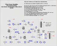
Thew have used a bridge rectifier on a center tapped 5V filament transformer and chose the values of 0.2R on each leg of the input into the bridge to drop the final voltage after rectification to 5V. If you look at the bottom right hand part of the schematic you can see this circuit.

I wanted to try this on a 2A3 amplifier I am building but what I cannot seem to figure out is what values of resistors I should use for the current and voltage the 2A3 draws on the filament. I understand Ohm's law pretty well but I can't seem to apply it here before the rectifier. I am sure it is pretty simple but I keep getting stumped.
The 2A3 draws 2.5A on the filaments whereas the 300B is 1.2A, the voltage is double for the 300B. I would think that the resistor values to do this for the 2A3 would be very close to what the 300B uses (0.2R) but again, I can't quite figure this out. Can anybody help me here?
Thanks,
Jeff
I have been trying to figure out how to adapt a circuit for DC filament heating found on the T-Rex amplifier.
Thew have used a bridge rectifier on a center tapped 5V filament transformer and chose the values of 0.2R on each leg of the input into the bridge to drop the final voltage after rectification to 5V. If you look at the bottom right hand part of the schematic you can see this circuit.
I wanted to try this on a 2A3 amplifier I am building but what I cannot seem to figure out is what values of resistors I should use for the current and voltage the 2A3 draws on the filament. I understand Ohm's law pretty well but I can't seem to apply it here before the rectifier. I am sure it is pretty simple but I keep getting stumped.
The 2A3 draws 2.5A on the filaments whereas the 300B is 1.2A, the voltage is double for the 300B. I would think that the resistor values to do this for the 2A3 would be very close to what the 300B uses (0.2R) but again, I can't quite figure this out. Can anybody help me here?
Thanks,
Jeff
"You are not authorized to view this page"
I suggest using some kind of free alternative that doesn't block access to its contents (i.e. Tinypic.com etc.) ... or better yet, just attach the relevant portion of schematic here as .PNG or .GIF file ("Manage Attachments" button in Advanced editing mode).
I suggest using some kind of free alternative that doesn't block access to its contents (i.e. Tinypic.com etc.) ... or better yet, just attach the relevant portion of schematic here as .PNG or .GIF file ("Manage Attachments" button in Advanced editing mode).
Well... You get 5 V(RMS) AC from the transformer. There'll be 1.4 V drop (two diodes) across the rectifier. Hence, I figure the voltage across the reservoir cap will stabilize around 1.3*(5-1.4) = 4.7 V. This is for R = 0 ohm.
You say 2.5 V filament @ 2.5 A... So you need (4.7-2.5)/2.5 = 0.87 ohm. You can split this up as 2x0.43 ohm if desired.
But ya know... The worst case input voltage is probably 5 V - 10 % or 4.5 V. (4.5-1.4)*1.3 = 4.0 V on the reservoir cap. 4.0 - 2.5 = 1.5 V -- plenty of headroom for an LDO regulator. There are plenty of 3 A LDO's around. Not only will this give you a filament voltage that's independent of mains voltage fluctuations, it'll also provide the best ripple reduction money can buy. The headroom might be a bit tight once you take the ripple voltage into account. I'll let you do the math. Or you can buy one of the $7 LDO's from LT that have 0.3~0.4 V drop-out. Or use a 6.3 V winding if you have one available.
Tom
That would be if I were using a 5VCT, but I have a 2.5VCT I was trying to calculate the resistor values on. So what you are saying is on the bridge I need to estimate a 1.4v drop across the bridge.....so 2.5 x1.4 = 3.5V without the voltage drop, so really with the voltage drop and the rectifier I will be at 2.1V without any resistors....hmmm, I forgot about that diode voltage drop. I could use a 5VCT with the 0.43 (0.44R rounded for what I have on hand) to get right at 2.5VDC.
OK, well thanks.....pretty much poopoo cans the idea of using a rectifier on my 2.5VCT transformers, guess I will just stick to the original design for this 2A3 project.
Thanks again,
Jeff
OK, well thanks.....pretty much poopoo cans the idea of using a rectifier on my 2.5VCT transformers, guess I will just stick to the original design for this 2A3 project.
Thanks again,
Jeff
Tom,
If I just used a 2.5VCT with a bridge rectifier and the caps like on the T-Rex design with no resistors, what would my voltage stabilize at after rectifying the 2.5VCT? Higher than 2.1? Is there any way to rectify something without as much voltage drop?
Jeff
If I just used a 2.5VCT with a bridge rectifier and the caps like on the T-Rex design with no resistors, what would my voltage stabilize at after rectifying the 2.5VCT? Higher than 2.1? Is there any way to rectify something without as much voltage drop?
Jeff
A note on your math in post #5. The sqrt(2) = 1.414 conversion factor from Vpeak to Vrms is correct, however, in order for a rectifier to rectify the voltage and arrive at exactly the peak voltage Vpeak = sqrt(2)*Vrms, the conduction angle needs to be zero and the current through the rectifier an infinite magnitude impulse. In real life, you end up with about 1.3*Vrms rather than sqrt(2)*Vrms on the reservoir cap. And the math I showed above is for a 5 V winding. I.e. 5 V RMS into the rectifier. It works for a 2.5 V CT winding as well, but instead of the 4.0 V on the reservoir cap, you end up with +2V on one cap and -2V on the other (using the numbers from my worst case calculation).
That aside, I don't know of a way to rectify 2.5 A with a voltage drop much lower than 0.5~0.7 V. A regular silicon rectifying diode (Si P-N junction) will have a forward drop of 0.6~0.7 V at low-ish currents and in many cases upwards of 1 V for higher current (amps). In addition the series resistance of the diode comes into play. See the diode spec sheet for more information - there's usually a Vf vs Id curve somewhere... Alternatively, use a Shottky diode (Si - metal contact). They have lower drop - usually around 0.5 V.
A bridge rectifier will cause a drop of 2*Vf or roughly 1.4 V. With a center-tapped winding, you could use a regular, two-diode full-wave rectifier with a drop of only 1*Vf. You'll lose the center reference so instead of being powered by +/-1.25 V as in the original schematic, you'll supply +2.5 V. The filament lights up the same, but the electron emission may be ever so slightly higher in one end of the filament than the other. If this is an issue, then you're back to square one.
Actually, now that I think about it, I think the resistor value I arrived at previously (2 x 0.43 R) would work just fine. It's fairly easy to verify this in pspice/ltspice/winspice/whateverspice.
~Tom
DC on the filaments
Well, I happen to have x2 5VCT filament transformers on hand, I could just use those and drop the voltage to the 2.5 like in the first calculation you showed. I understand with the lower voltage filaments that the difference between AC and DC becomes less apparent. It is probably not a big deal. I will probably just stick with Hagerman's original design, he calls it a balanced cathode drive. Basically using the centertap as the path to ground for the cathode resistor. I was wondering about this, he says there is no need for a hum pot b/c of this set up.....does it work that well? Or am I better of going with the more traditional (maybe it isn't traditional) hum pot circuitry? This is my first DHT amp and I probably ought to stick with the original design at first anyway. It always seemed to me that using DC on the filaments of a DHT should be quieter but again, my assumptions have proven wrong in the past. BTW the amp I have started to build is the Hagtech Clarion
http://www.hagtech.com/pdf/clarionarticle.pdf
This is where I was planning on trying this circuit like on the T-rex with the filaments.
I will probably build it like he did and if I want to try something different it should not be too difficult to swap the 2.5VCT for a pair of 5VCT and add the rectifier/caps/resistors later.
Thanks for helping me with the math, seems as soon as I think I have my mind around this stuff I get a curveball thrown at me.
Sincerely,
Jeff
Basically using the centertap as the path to ground for the cathode resistor. I was wondering about this, he says there is no need for a hum pot b/c of this set up.....does it work that well?
The two windings (outermost ends to CT) work as an extremely low impedance voltage divider, just like a low value potentiometer would but without additional losses in potentiometer. Provided that transformer windings are symmetrical around CT, this works just as well or better as/than any potentiometer could and sets filament precisely around CT (which is referenced to ground potential).
If I were you I'd try the AC option first with your 2.5 CT heater winding. If and only if there is audible heater hum induced by the heater would I consider DC alternatives (more precisely: CCS).
- Status
- Not open for further replies.
- Home
- Amplifiers
- Tubes / Valves
- Help figuring out resistor values