Hello guys,
What im trying to do is to understand where the audio line goes, start from left of the image.
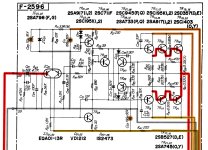
Its Sansui AU-5900 schematic. Board F-2605, I crop the image to make smaller, only left channel.

Far right at R59 and R61 im sure is the output to the relay and speaker.
Notes:
Red: Audio left channel
Orange: Audio Right Channel
Grey: Ground
Brown & Light Brown: Power +
Yellowish Brown & Light : Power -
Im stuck from IC01 2SA798
IC01 2SA798 pinout:

Im trying to do like what was in schematic of Sansui AU-D7:
(The red audio line is exist in schematic)

You can just mention the component number trough TRxx or Rxx.
Thank you very much for the help. And forgive me that i also post same question in another forum, i think maybe here is more DIYers.
And i will update this when i get the answer from another forum.
What im trying to do is to understand where the audio line goes, start from left of the image.
Its Sansui AU-5900 schematic. Board F-2605, I crop the image to make smaller, only left channel.
Far right at R59 and R61 im sure is the output to the relay and speaker.
Notes:
Red: Audio left channel
Orange: Audio Right Channel
Grey: Ground
Brown & Light Brown: Power +
Yellowish Brown & Light : Power -
Im stuck from IC01 2SA798
IC01 2SA798 pinout:
Im trying to do like what was in schematic of Sansui AU-D7:
(The red audio line is exist in schematic)
You can just mention the component number trough TRxx or Rxx.
Thank you very much for the help. And forgive me that i also post same question in another forum, i think maybe here is more DIYers.
And i will update this when i get the answer from another forum.
Attachments
Last edited:
Right channel as it is easier to read. From left input mirror transistor to R08, to TR04, from TR04 to TR02, then both from R24 to TR12 and TR04 to TR14.
Feedback is from R20 to C10/R14 and the base of the right input mirror transistor. First time I see dual transistors being called an IC but maybe I did not put attention to that.
Tip: use 1 µF 50V 5 mm pitched film Wima MKS2 caps for C01/C02/C17/C18, 10 µF 50V Pana FC/FR for C05 and C06, Nichicon 100 µF 25V MUSE ES bipolar for C09 and C10, Pana FR 100 µF 50V for C11/C12/C23/C24. If higher voltage electrolytic caps fit better because of exact same physical dimensions use those so 100 µF 35 V instead of 25V etc. Measure instead of assuming. Do not have too large non fitting caps dangling in the air. Never extend lead wires.
Last edited:

Wow thats so fast, thank you so much @jean-paul .
And also thankyou for your tips. Really appreciate that.
Yeah a view vintage amp called them IC, im confused too at first.
I redraw the line, is this correct?
Light Orange dashed is feedback.

And also thankyou for your tips. Really appreciate that.
Yeah a view vintage amp called them IC, im confused too at first.
I redraw the line, is this correct?
Light Orange dashed is feedback.
Seems about right.
C07/C08 better not be the then often used disc type ceramic caps but choose C0G/NP0 TH ones of today. You can remove C03/C04 and use Wima MKS2 5 mm 1.5 µF 50V for C01/C02.
Loudspeaker relay likely is shot too. Replace for one with hard silver minimum 8A rated contacts. Difficult task because of the now unusual format. A small adapter PCB may be necessary.
Last edited:
Thankyou again for your tips. You are like Audio Shaman, you can read my mind... lol... I did put notes what to replace.
Can i ask you another question? it is still in the same amp.

S01a is "Tone Defeat" switch, default is 1 as in schematic. Usually, i never use tone, so i prefer "defeat". Since i want to cut cost what i dont use,
I draw red line as default audio left channel,
Purple is when the switch is on, is that purple line correct?
Im trying to identify the caps. I dont want to waste a good cap in the path that i dont use.
Like C01 im sure it is the default path, so i will replace it with WIMA.
Can i ask you another question? it is still in the same amp.
S01a is "Tone Defeat" switch, default is 1 as in schematic. Usually, i never use tone, so i prefer "defeat". Since i want to cut cost what i dont use,
I draw red line as default audio left channel,
Purple is when the switch is on, is that purple line correct?
Im trying to identify the caps. I dont want to waste a good cap in the path that i dont use.
Like C01 im sure it is the default path, so i will replace it with WIMA.
As I hate scratchy switches/potentiometers, excess coupling caps and excess features I would cut out all the stuff plus rewire volume control. It would be good to check gain structure and see if it indeed has too much gain (and can do without its preamp section) and adapt it to 2Vrms sources. Also I would remove the often failing speaker A/B/A+B switch. Then make a new front cover sheet to cover the holes. So I can not advise.
Last edited:
- Home
- Source & Line
- Analog Line Level
- Help Draw Audio line or path in this amplifier PCB