Hi everyone, hope all is well. My monoblocks have been performing well until this afternoon. The Right channel plays louder than the Left. So, I started measuring and here is what I found:
I tried switching the driver tubes, same issues with the LEFT channel being lower B+ and Ua. Then I tried switching the driver tubes, same issue with the LEFT channel being lower B+ and Ua. So, the issue stays with the amp and not with the tubes.
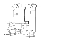
As a side not, B+ on the output tube is the same for both amps, so the output circuit is behaving. The output has its own power supply. So, this leads me to believe that the driver power supply is where we have an issue. Schematic attached.
Thoughts?
| Left | Right | |
| B+ @ Rectifier Vdc | 355 | 376 |
| Ua @ driver Vdc | 314 | 367 |
| Bias @ driver Vdc | 3.65 | 3.86 |
| Rectifier filament Vac | 4.02 | 4.19 |
| driver filament Vdc | 4.71 | 4.77 |
I tried switching the driver tubes, same issues with the LEFT channel being lower B+ and Ua. Then I tried switching the driver tubes, same issue with the LEFT channel being lower B+ and Ua. So, the issue stays with the amp and not with the tubes.
As a side not, B+ on the output tube is the same for both amps, so the output circuit is behaving. The output has its own power supply. So, this leads me to believe that the driver power supply is where we have an issue. Schematic attached.
Thoughts?
Attachments
Last edited by a moderator:
Can't really help you but love the use of the 866 rectifiers!
You say B+ is lower on the right but your chart says otherwise. Also, you say the R output is higher. Are both these things correct?
You say B+ is lower on the right but your chart says otherwise. Also, you say the R output is higher. Are both these things correct?
Are you certain they used to measure the same?
Can you measure the signal gain at say the second grid,
and not just the DC voltages?
Can you measure the signal gain at say the second grid,
and not just the DC voltages?
Did you mean you tried swapping the rectifier tubes in your first post? Have you measured the AC voltage into the rectifier?
Jaytor - I did swap the rectifier tubes, yes. The measured Rectifier Vac is as follows: LEFT 4.02Vac. Right 4.19Vac.
Rayma - I am certain the B+ and the Ua used to measure the same (+/- 5Vdc).
The Vac at the driver grid = 18mV (1K sine wave). Both sides measure 18mV.
The Vac at the output grid LEFT = 410mV. RIGHT = 580mV.
Rayma - I am certain the B+ and the Ua used to measure the same (+/- 5Vdc).
The Vac at the driver grid = 18mV (1K sine wave). Both sides measure 18mV.
The Vac at the output grid LEFT = 410mV. RIGHT = 580mV.
Rayma - before I swap the IT, what about the Ua and B+ differences? Is that the culprit rather than the IT? Please help me understand/rationalize.
You've swapped the driver tubes, and the cathode resistors give about the same DC bias voltage.
So the Ua difference could be due to a problem in the IT. At this point you have to rule the IT out.
The signal gain is not directly related to the B+ value, certainly not with a 3dB difference.
Just measure the driver signal outputs after swapping the ITs, so you can compare the readings.
Assume this signal is at 1kHz?
Last edited:

| Bias @ driver Vdc | 3.65 | 3.86 |
If the bias voltage is higher on right channel, then current is lower than in left channel, so lower current may occurs higher B+.
Try to balance bias voltages.
Is the power rating of your bleeder resistors sufficient? That 10k bleeder has about 16W across. A bleeder damaged by overheating could change value enough to cause that imbalace.
Can you measure the DC drop across L2 choke of both channels and compare? That will be an indicator for the drawn current. If one stage draws higher current than the intended, this is a probable explanation.
Did you check AC voltages across transformer secondaries (careful)!
Did you check AC voltages across transformer secondaries (careful)!
OK, this is very interesting. I pulled the output and driver tube. The B+ and driver Ua were both 481Vdc on BOTH tubes (regardless of which IT is being used). I confirmed that the bleeder resistors are OK. So I switched the ITs. The problem still stayed with the LEFT monoblock regardless of which IT is used.
Then, it dawned on me. I was testing different driver filament supplies. With some newly acquired linear supplies, both tubes were measuring ~4.7Vdc. Output was good on both channels So, I thought all was OK. I had music that had good output for about 3 days, then the issue started which is why I posted this post. Then, in a moment of desperation, I replaced the temporary supplies with batteries for driver filaments. This cured the issue. Both monoblocks have B+ 378Vdc and Ua 367Vdc.
So, how can the filament supply change the B+ and Ua?
Just to clarify, the cure was due to replacing the linear power supply with batteries.
Problematic: 18Vac transformer --> LPS --> Vdc filaments.
Cure: Batteries --> regulator --> Vdc filaments.
Last edited by a moderator:
From what you have showed us the output tube is completly independent from driver , so B+ shouldn't be affected ... if it did really changed is very possible that the schematic is not like that , or the 2 filament supplies are not wired correctly
Also the minus from driver filament supply shouldn't be on the other side of bias resistor ?
Also the minus from driver filament supply shouldn't be on the other side of bias resistor ?
Last edited:
B+ is completely separate between output tube and driver tube. Dual power supplies. The minus on the driver filament supply is intentional on the other side of the resistor, as this is called Filament Bias.
- Home
- Amplifiers
- Tubes / Valves
- help: B+ differences between monoblocks