You should trim the values by adding much smaller caps in parallel. Let's say that your 4.9nF actually measured 4.8nF and you need 5nF, then a measured 200 - 220pF cap would be placed in parallel to get as close as possible to the required value.
In fact the closest standard value is likely 4.7nF, so measure its value and chose a small cap (maybe a 300pF to 470pF depending on what you measured) in parallel.
Do the same thing for the 1.5nF, possibly a 1.2nF//270 - 330pF as an example.
100pF is a small, but significant error out of 5nF.
In fact the closest standard value is likely 4.7nF, so measure its value and chose a small cap (maybe a 300pF to 470pF depending on what you measured) in parallel.
Do the same thing for the 1.5nF, possibly a 1.2nF//270 - 330pF as an example.
100pF is a small, but significant error out of 5nF.
You should trim the values by adding much smaller caps in parallel. Let's say that your 4.9nF actually measured 4.8nF and you need 5nF, then a measured 200 - 220pF cap would be placed in parallel to get as close as possible to the required value.
In fact the closest standard value is likely 4.7nF, so measure its value and chose a small cap (maybe a 300pF to 470pF depending on what you measured) in parallel.
Do the same thing for the 1.5nF, possibly a 1.2nF//270 - 330pF as an example.
100pF is a small, but significant error out of 5nF.
It is time for me buy a capacitance (or LCR meter)! I agree with your comments! But How do I know if the designer of the circuit did not use 'close values himself: 1.5 and 5nF in this case)? Let's imagine the computed value was 4,9 and the guy had 5nF on the shelf. Well the 'guy' is Akihiko Kaneda!
Sorry for my English!
Well done so far, and your English is fine!
You need to look up and study how a parallel C and R relates to a "pole" in the frequency response, and a "time-constant" in the time domain. These are two different ways of looking at the same thing.
Google "theory of RIAA response", "time constants" in analog circuits.
A bit of study and it will "click" Eureka!
Keep asking questions! No questions are foolish, but some answers are 😱
Well done so far, and your English is fine!
You need to look up and study how a parallel C and R relates to a "pole" in the frequency response, and a "time-constant" in the time domain. These are two different ways of looking at the same thing.
Google "theory of RIAA response", "time constants" in analog circuits.
A bit of study and it will "click" Eureka!
Keep asking questions! No questions are foolish, but some answers are 😱
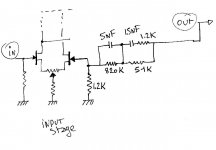
Do you mean that I can' 'easily' calculate or check the values by myself? Do the output stage characteristics has an influence on the values of the RIAA
network?
Yes, the feedback network (Series R//C) has a particular impedance at any particular frequency. Long way is to do a 1/(2 Pi f C) for each Cap. Quicker is to learn how to use a simulator 🙂
So the network can be modelled as an impedance or "resistor" for that frequency, which, in combination with the 1.2K input resistor gives a certain gain. As the frequency varies, so does the gain. Following a curve which was defined by the RIAA ...
Read, Study ...
So the network can be modelled as an impedance or "resistor" for that frequency, which, in combination with the 1.2K input resistor gives a certain gain. As the frequency varies, so does the gain. Following a curve which was defined by the RIAA ...
Read, Study ...
Yes, the feedback network (Series R//C) has a particular impedance at any particular frequency. Long way is to do a 1/(2 Pi f C) for each Cap. Quicker is to learn how to use a simulator 🙂
So the network can be modelled as an impedance or "resistor" for that frequency, which, in combination with the 1.2K input resistor gives a certain gain. As the frequency varies, so does the gain. Following a curve which was defined by the RIAA ...
Read, Study ...
Yes dad!

That is unnecessarily offensive - so go and wipe your own bottom.
No smiley
So you can see that my English is bad! Sense of humour is very different depending on countries. Here is Switzerland it is a friendly way to say that we agree but we not happy to do what we have to do! Just kidding you say? Sorry for that.
Actually, it would be more helpful to give you some pointers, so:
Cut and Thrust: RIAA LP Equalization | Stereophile.com
and
RIAA equalization - Wikipedia, the free encyclopedia
should be a starting point.
And, BTW, that should be Grand-dad!
Cut and Thrust: RIAA LP Equalization | Stereophile.com
and
RIAA equalization - Wikipedia, the free encyclopedia
should be a starting point.
And, BTW, that should be Grand-dad!
My bad, as they say. Apologies to you for over-reacting.
Now - get on with your studies!! 😀
Yes!
And this is where I should have pointed you, if you just want to "get it done"
http://www.diyaudio.com/forums/analogue-source/77558-riaa-component-calculator.html
http://www.diyaudio.com/forums/analogue-source/77558-riaa-component-calculator.html
And this is where I should have pointed you, if you just want to "get it done"
http://www.diyaudio.com/forums/analogue-source/77558-riaa-component-calculator.html
Great link. I think I can experiment on my own. Thanks a lot!
Cheers,
Measuring and tweaking the values for best adherence to the curve is the technique that may work best for you. Since it is a feedback based design overall loop gain plays a role in accuracy as well, modeling will only get you so far..
Is that Ja!, Oui or Si ?
Which Canton are you from?
It is 'oui'. I am living in a french speaking canton called 'Le Vaud' between Geneva and Lausanne. ( I was born in France actually)!
Ha!
I had relatives living in Chesieres / Villars sur Ollon for many years - i spent many wonderful holidays there
I had relatives living in Chesieres / Villars sur Ollon for many years - i spent many wonderful holidays there
- Status
- Not open for further replies.
- Home
- Source & Line
- Analogue Source
- Help! A RIAA expert wanted!!!!!!