Hi.
My first pair of loudspeakers were purchased when I lived in England and are about ten years old (lordy!). Two years ago, I used them as part of the entertainment system at our wedding reception and due to the temporary nature of the wiring, a short occurred across the speaker terminals.
Surprisingly the amp (a little Denon UD-M31) didn't bat an eyelid and is still doing sterling service as we speak. The loudspeaker in question, on the other hand didn't like it and instantly expired. I am just now getting time to investigate what blew.
When connecting to an amp, the other speaker works fine, but this one gives absolutely no output. The drivers show no visible damage and there was no audible sign that one channel had gone so I am assuming the problem lies with the crossover.
I have a basic knowledge of electronics and am the proud owner of a soldering iron, screwdrivers and enough enthusiasm to be dangerous! I am hoping that someone here may be able to help guide me through the process of troubleshooting and repairing what are a sentimentally valuable pair of speakers.
Here is a review of the speakers to give you a very basic idea of what they are:
http://www.audioreview.com/mfr/castle-acoustics/floorstanding-speakers/PRD_119282_1594crx.aspx
Here is a photo of the crossover (I hope I have identified the components correctly)
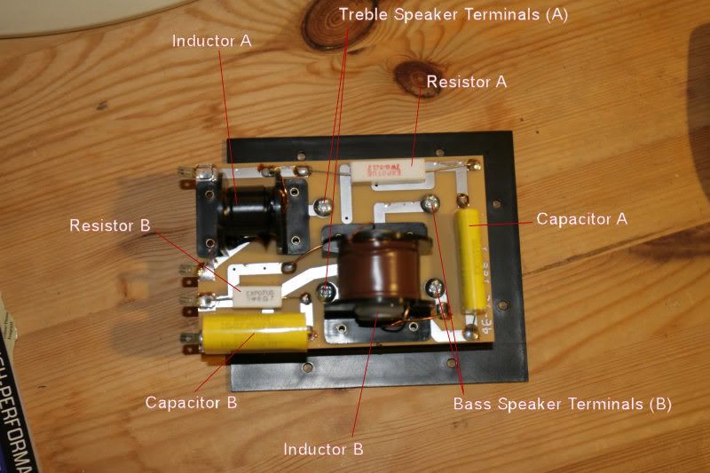
Components are labelled as follows:
Inductor A no label
Resistor A Expotus 7W 6.8ohms J
Capacitor A Expotus 4.7J 250V MPP
Inductor B no label
Resistor B Expotus 5W 6ohms J
Capacitor B Expotus 10.0J 250V MPP
Using my multimeter, the resistors appear to measure correctly, but I don't know how to test the caps or the inductors. I would expect to get continuity for the inductors, but don't - is that my meter or something else?
Any and all assistance with working out what's dead would be very much appreciated.
Thanks
James
My first pair of loudspeakers were purchased when I lived in England and are about ten years old (lordy!). Two years ago, I used them as part of the entertainment system at our wedding reception and due to the temporary nature of the wiring, a short occurred across the speaker terminals.
Surprisingly the amp (a little Denon UD-M31) didn't bat an eyelid and is still doing sterling service as we speak. The loudspeaker in question, on the other hand didn't like it and instantly expired. I am just now getting time to investigate what blew.
When connecting to an amp, the other speaker works fine, but this one gives absolutely no output. The drivers show no visible damage and there was no audible sign that one channel had gone so I am assuming the problem lies with the crossover.
I have a basic knowledge of electronics and am the proud owner of a soldering iron, screwdrivers and enough enthusiasm to be dangerous! I am hoping that someone here may be able to help guide me through the process of troubleshooting and repairing what are a sentimentally valuable pair of speakers.
Here is a review of the speakers to give you a very basic idea of what they are:
http://www.audioreview.com/mfr/castle-acoustics/floorstanding-speakers/PRD_119282_1594crx.aspx
Here is a photo of the crossover (I hope I have identified the components correctly)
Components are labelled as follows:
Inductor A no label
Resistor A Expotus 7W 6.8ohms J
Capacitor A Expotus 4.7J 250V MPP
Inductor B no label
Resistor B Expotus 5W 6ohms J
Capacitor B Expotus 10.0J 250V MPP
Using my multimeter, the resistors appear to measure correctly, but I don't know how to test the caps or the inductors. I would expect to get continuity for the inductors, but don't - is that my meter or something else?
Any and all assistance with working out what's dead would be very much appreciated.
Thanks
James
one thing to try is to wire each speaker one by one just directly to the amp to see if you get output (without the crossover) that way you can be certain if it's the crossover or not.
Yes, the inductors should have a resistance of less than perhaps 10 Ohms.
I assume you know that the inductor wire has an enamel insulation, so you can only easily measure from the board foil at the input and output of the inductors. That said, a blown inductor would usually show signs of a lot of heat, and I don't see that.
Caps need a special instrument, but when you connect the ohmmeter you should see a small "kick" of the needle (?) or flicker of the digits as the cap charges very briefly when connecting the meter.
Could there be a fuse tucked away somewhere? If you connect the ohmmeter or a 1.5 Volt battery directly across each driver, do you hear a small click? (Ohms X 1 Scale.)
dark_avenger said:one thing to try is to wire each speaker one by one just directly to the amp to see if you get output (without the crossover) that way you can be certain if it's the crossover or not.
Yes try this approach first but at very low volume level with the tweeter. If the speakers don't work they are bad.
A super easy way to see if the speakers are working is to brush the leads to the speakers across the terminals of a 9 volt battery. You should hear a click as was described above. But don't try this with the tweeter, it may damage it.
jw2k_fr said:
...... a short occurred across the speaker terminals.
Surprisingly the amp (a little Denon UD-M31) didn't bat an eyelid and is still doing sterling service as we speak.
The loudspeaker in question, on the other hand didn't like it and instantly expired.
I am just now getting time to investigate what blew.
Thanks
James
Hi,
A short across a speakers terminals cannot damage a speaker.
Whatever the problem is there seems to be some misunderstanding.
Swapping the crossover boards between the speakers will help.
🙂/sreten.
Use a 1.5V battery to be safe.
To check the drivers, check the VC resistance using a DMM on the +ve and -ve terminals. That will give a good indication if it's an open (no reading) or closed circuit (0R). Look for a reading between 3R & 8R if OK (assuming they are a 4R-8R driver).
To check the drivers, check the VC resistance using a DMM on the +ve and -ve terminals. That will give a good indication if it's an open (no reading) or closed circuit (0R). Look for a reading between 3R & 8R if OK (assuming they are a 4R-8R driver).
Re: Re: Help a poor noob pls!
Hmmm, I may wait a bit on this one - don't want to risk any un-necessary damage (I'm so new to this I am a little paranoid)
Oooh - yeah enamelled wires 🙂 That made a difference. Am seeing a resistance of about 0.6ohms for one inductor and 0.8ohms for the other.
No sign of any fuses - you can see all the components from the photo - nothing under the circuit board other than the speaker terms.
Hmmm don't have a 9v at the mo, will wait a bit for that one
The short occurred across the speaker terms of the amp whilst connected to the speakers - arcing was seen so I assume that the current flow went way up....
I will indeed swap the crossover boards - the simplest ideas are always the best!
They should be 8ohm, but I get no reading - let's see what the crossover swap reveals. (I really hope the drivers are okay)
Thanks again!
dark_avenger said:one thing to try is to wire each speaker one by one just directly to the amp to see if you get output (without the crossover) that way you can be certain if it's the crossover or not.
Hmmm, I may wait a bit on this one - don't want to risk any un-necessary damage (I'm so new to this I am a little paranoid)
Curmudgeon said:I assume you know that the inductor wire has an enamel insulation, so you can only easily measure from the board foil at the input and output of the inductors. That said, a blown inductor would usually show signs of a lot of heat, and I don't see that.
Could there be a fuse tucked away somewhere? If you connect the ohmmeter or a 1.5 Volt battery directly across each driver, do you hear a small click? (Ohms X 1 Scale.) [/B]
Oooh - yeah enamelled wires 🙂 That made a difference. Am seeing a resistance of about 0.6ohms for one inductor and 0.8ohms for the other.
No sign of any fuses - you can see all the components from the photo - nothing under the circuit board other than the speaker terms.
Hezz said:A super easy way to see if the speakers are working is to brush the leads to the speakers across the terminals of a 9 volt battery. You should hear a click as was described above. But don't try this with the tweeter, it may damage it. [/B]
Hmmm don't have a 9v at the mo, will wait a bit for that one
sreten said:Hi,
A short across a speakers terminals cannot damage a speaker.
Whatever the problem is there seems to be some misunderstanding.
Swapping the crossover boards between the speakers will help.
🙂/sreten.
The short occurred across the speaker terms of the amp whilst connected to the speakers - arcing was seen so I assume that the current flow went way up....
I will indeed swap the crossover boards - the simplest ideas are always the best!
rabbitz said:Use a 1.5V battery to be safe.
To check the drivers, check the VC resistance using a DMM on the +ve and -ve terminals. That will give a good indication if it's an open (no reading) or closed circuit (0R). Look for a reading between 3R & 8R if OK (assuming they are a 4R-8R driver).
They should be 8ohm, but I get no reading - let's see what the crossover swap reveals. (I really hope the drivers are okay)
Thanks again!
Dag-nammit !
It appears that the crossover is fine and both drivers may be dead. I was really hoping to avoid that given how they are an unusual shape surround for the woofer.
*sigh* Guess I'll have to contact the factory regarding replacements.
However, on a similar note... I also have a pair of Castle Harlech S2 speakers which I upgraded to, from the Avons. The Harlechs are a measure less veiled than the Avons although both are very musically engaging. I wondered about upgrading the internal wire and perhaps the caps in the crossover. I've read a number of articles about replacing standard caps with Black Gates etc and wondered whether this might open up the sound to a degree?
Are there other components worth replacing? I don't feel confident to do the inductors as they are affixed to the circuit board, but what about the resistors?
I suppose I could consider replacing the drivers too, but given that the speaker was voiced with this cabinet in mind, I would be concerned about totally mucking up what the speaker does well.
Any thoughts?
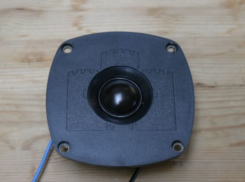
Okay, I've extracted the tweeter from the cabinet:
Front:
Rear:
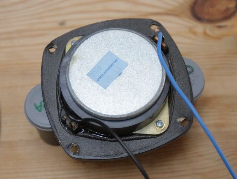
Nothing really to see - no signs of scorching etc. I get an open circuit across the terms. I am assuming that the delicate wires in the voice coil have probably fried?
What likelihood is there of getting these drivers repaired as opposed to replaced?
Front:
Rear:
Nothing really to see - no signs of scorching etc. I get an open circuit across the terms. I am assuming that the delicate wires in the voice coil have probably fried?
What likelihood is there of getting these drivers repaired as opposed to replaced?
If the manufacturer still has voice coils for the drivers, your in luck. If they have complete driver replacements in stock, your even luckier. If no to both of the above, time to write an obituary.
jw2k_fr said:Okay, I've extracted the tweeter from the cabinet:
Nothing really to see - no signs of scorching etc. I get an open circuit across the terms. I am assuming that the delicate wires in the voice coil have probably fried?
Fried voice coil.
It is strange, though, that the woofer also blew up. Woofers usually tolerate more abuse
Some amps oscillate when shorted. For instance, that happened to me on a TDA7294 amplifier. When it shorted I heard a burst of high frequency sound (about 4-10 kHz) and the chip burst into flames. This kind of oscillation would have burnt a tweeter. My 50 watts 8 ohm test resistor survived, though.
Hooooooo boy.... nothing like this is ever easy....
So it turns out that Castle Acoustics went into receivership last November and have been purchased by the IAG group who run Quad, Mission and others. IAG currently recommend a gentleman by the name of Mike Laister for repair work (he's been dealing with them for 30 years!) (+44 1904 761043) and he can repair the drivers and voice coils. However, if I factor in shipping and the repair, I would be looking at the wrong end of $400+ which is a tad steep. I could buy a pair of Castle Severns on Audiogon for $400 in CA, except they're not open to shipping.
When the company bones were picked over last year, someone bought up the entire company inventory, but not even Andrew Hill, the guy at Castle who used to do factory repairs knows who it was, so that option seems to be unavailable. It seems as if I might be best served by watching on eBay or Audiogon for a pair and seeing what they go for.
Ugghh, so much for an easy fix. I really hate to write these off as I love them dearly. Anyone with any suggestions for other avenues to try?
Thanks
James
Progress
It turns out that May Audio have some old stock of drivers including the two models I need - Tweeter #813 and woofer #634 (numbers on rear of drivers). $180 including tax and shipping seems vaguely reasonable for OEM stock so I pulled the trigger and hope to have them by the end of the week. I know that's more than drivers used for a lot of the projects here, but I didn't want to try attacking the cabinets with a router - THAT would have been a recipe for disaster given my lack of experience...
Now if only I could get some recommendations on tweaks to make to the crossovers (yes, I'm subtle, I know 🙂)
Your crossovers look decent, those are film caps, coils are perpendicular...
You might try to replace the coils with air-core coils (available in any audio parts shop, don't go for super-fancy stuff, just coiled copper wire on a plastic bobbin, lol).
Check the values of course !!!
(LCR meter comes in handy, if you don't have one, the guy from the shop will)
When testing speakers after a change of crossover, use a very low volume (in case you messed up), better now blow another tweet !
As for the capacitors, you may try to replace them too, but don't spend megabucks. Megabucks are better spent on a better source than on silver caps wound by naked geishas.
Ah, the joys of many cooks, one soup.
I'd suggest leaving the inductors, UNLESS you occasionally hear a "crack" during loud passages, which would indicate core saturation. Keeping the DC Resistance roughly the same with an air core coil will make it pretty large.
I'd substitute a Mills resistor for the sandcast resistor, and I'd check out someplace like these forums or http://www.humblehomemadehifi.com/ for capacitor recommendations. Polypropylene, and I'd prefer foil to film, but there are size and cost considerations...
I, and many others, find that you need to break in capacitors before you can make a final decision; forty hours at a bit higher level than normal is a good rule of thumb. If possible, don't listen during the breakin period, for a better evaluation.
Back in black
So, my studies are almost done and I should be able to get stuck into this in a couple of weeks.
As an update, I got the first pair of drivers from May audio and found that the woofer was faulty (judging by the packing I am guessing that a damaged unit must have accidentally been put back into stock). They were really good though and shipped me a replacement right away. I soldered them up and all was good - I was totally stoked!
Ironically, I lent the speakers to someone for another wedding and his DJ popped the voice coil in one of the woofers again! So... I will have to order ANOTHER woofer (and I doubt I will lend them out again!)
I have also got myself a decent LCR meter and have found out the following:
Inductor A measures 0.333mH
Inductor B measures 1.84mH
I am having a little trouble measuring the caps as the digital meter I have doesn't really give me an accurate measurement. Any suggestions?
I have browsed parts express and wondered whether anyone would recommend Jantzen 15gauge or the Erse 14gauge coils?
The cost differential isn't much between either option, but wondered if anyone had experience of either or both?
http://www.partsexpress.com/air-core-inductors.cfm
Also, which is likely to make a greater change?
The resistors?
The inductors?
The capacitors?
I know that each crossover is different, just wondered what peoples' opinions were based on their experience?
Thanks again in advance for your help, insight and comments!
I don't think there would be a significant difference between the Jantzen and Ersa coils; choose the ones that most closely match the DC resistances of your current coils.
I would expect the resistor AND capacitor to make a larger difference than the inductors. I'd change both. I've had good luck with the Mills resistors, others with some of the Caddocks. Either will be smoother and better defined than the sand cast cheapies.
Capacitors; well there's been a lot of info available on caps here on these forums; my favorite budget caps, the North Creeks are no longer available, but there's a lot of good info at the humble site.
Humble Cap Reviews
Have you disconnected one end of the cap from the crossover before trying to measure? Sticking with the labeled values, which I believe are 4.7 and 10 uF, should be ok; an exact match to an existing, for example, 4.681 uF won't be necessary; 5% tolerance should be fine.
I guess MPP is Metalyized polypropylene??? If so, the existing caps may be decent.
You might want to consider replacing what appears to be a steel mounting plate with a plastic or aluminum one. I distrust steel/ferrous metals, especially as you are going to air core coils, which have a larger magnetic field coverage volume than cored coils. Ordinary steel (not designed for use in magnetic applications) tends to have hysteresis and nonlinear loss issues.
G'luck, and let us know. 😉
About time...
So, it's only been about 20 months since I last posted....
Today I finally decided it was time to get my finger out and get the crossovers upgraded. I have had the parts for about 18 months and singularly failed to do anything with them!
Anyway, I went ahead and desoldered all the old components from the board. I thought about trying to do point-to-point wiring, but I didn't want to risk making a mistake. I ended up soldering everything back onto the same boards.
I was extremely nervous as I hit play and turned the volume up from zero....... and it works!!!! I M geeneeyus! Ahem... well not quite, but I am sure some of you can remember your first upgrade 😉
First impression was that they sound the same (okay so nothing is run in yet), but I take that as a good thing - I didn't appear to make a mistake in matching components. After half an hour, it would seem that the new one is a little louder and a measure less veiled than the old one. It remains to be seen how things unfold over the next few months.
I will take pictures of the old and new components and my ghetto crossovers later today 🙂 (I have little bubblewrap pads supporting the inductors 😛)
Thanks again to everyone who responded. I am pretty stoked - it was fun to do and I like the result. What else can you ask for?
- Status
- Not open for further replies.
- Home
- Loudspeakers
- Multi-Way
- Help a poor noob pls!