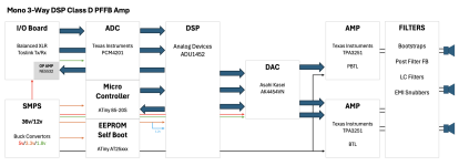
I'm in the process of building some 3-Way Studio Monitors which would require approximately 2x100W + 1x200W @ 4Ohms, with DSP that would work with both Balanced and Digital inputs.
With the prices of the Fusion FAX53 Amps, I've been plugging away for weeks on KiCad and I believe I'm 90-95% there with a schematic, but wanted to get some feedback as to whether or not its a decent design, if there are any errors in my thinking and any other general considerations that I should probably be making?
I've attached the block diagram for reference questions and comments are all welcome, bearing in mind I have as close to zero knowledge in this field other than what has been learned along the way.
Attachments
Conceptually, this is a working solution.
Another matter is the implementation. There has always been a problem of matching analog circuits with pulse circuits. In your case, a lot will depend on the topology of the printed circuit board and the placement of certain components of the circuit on it. Most often, when placing pulse amplifiers next to each other, both the ADC and DAC lead to an unacceptable noise level associated with the influence of interference from pulse amplifiers on the low-power circuits of the ADC and DAC. If you have never matched low-current circuits with pulse current consumers, then you have a very small chance of getting an acceptable result the first time.
Another matter is the implementation. There has always been a problem of matching analog circuits with pulse circuits. In your case, a lot will depend on the topology of the printed circuit board and the placement of certain components of the circuit on it. Most often, when placing pulse amplifiers next to each other, both the ADC and DAC lead to an unacceptable noise level associated with the influence of interference from pulse amplifiers on the low-power circuits of the ADC and DAC. If you have never matched low-current circuits with pulse current consumers, then you have a very small chance of getting an acceptable result the first time.

Was my reasoning in thinking I'd no doubt need to enlist some help for the PCB design... 👍🏾Conceptually, this is a working solution.
Another matter is the implementation. There has always been a problem of matching analog circuits with pulse circuits. In your case, a lot will depend on the topology of the printed circuit board and the placement of certain components of the circuit on it. Most often, when placing pulse amplifiers next to each other, both the ADC and DAC lead to an unacceptable noise level associated with the influence of interference from pulse amplifiers on the low-power circuits of the ADC and DAC. If you have never matched low-current circuits with pulse current consumers, then you have a very small chance of getting an acceptable result the first time.
I'm really interested to know who's ready to take on such a task.Was my reasoning in thinking I'd no doubt need to enlist some help for the PCB design...
I think the most realistic way is to take some finished product as a basis. Doing everything from scratch is very difficult.