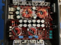
My name is Patrick, I live in Des Moines, IA. I’m originally from Grand Rapids, MN. I’m trying to get into repairing car amplifiers, and am attempting some repairs, have set up a bench testing station and repair station in my house. I’m excited to talk with people here, and really looking forward to learning some things from you guys who are experienced in this field. Does anyone know a good site to use for schematic diagrams by chance? I’m having a tough time finding a schematic for a Sundown Audio SAE-1500D v3. It flashes protection light when powered up. It looks like it has a burned diode (Marking says S30) on the 12v Offset Protection Circuit. I included a picture, in case anyone can confirm that this is indeed what I’m looking at? I got this amp off EBay to repair and to start learning the trade better.
Thanks,
Patrick
Thanks,
Patrick
Attachments
Do you have a bench power supply with current limit capability?
The diode may be blown by a fault in itself or by another external condition. Try to remove and clean the area and verify the surrounding components both passive (Diodes, resistances, etc.) and active (BJT, MOSFET's, etc).
The diode may be blown by a fault in itself or by another external condition. Try to remove and clean the area and verify the surrounding components both passive (Diodes, resistances, etc.) and active (BJT, MOSFET's, etc).
If that diode connects between the B+ and ground, it's a Reverse Protection (RP) diode and someone likely connected it with reverse polarity.
Remove it and measure the resistance between the B+ and ground and post what you read.
What are the part numbers on the face of the PS and output FETs?
Are any of the output FETs shorted?
https://elektrotanya.com/?q=keres
^^^ that's generally a decent site for diagrams but this looks like a Brazilian clone and I doubt that you'll find anything for it.
That is indeed a reverse polarity protection diode as Perry pointed out.
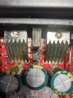
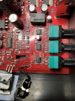
It's not clear from the picture but it looks like one of the output drive ICs is also damaged. (16 pin IC near the potentiometers.)
If you're serious about fixing amps and this isn't a 1 off, buy Perry's tutorial. The extras in there alone are worth more than he charges for the whole thing.
I'm not sure how much info is in there on the Brazilian style amps as I'm still using the version I bought in 2020 but it's a goldmine regardless.
Welcome to the forum.
If you want the latest version (many changes), email me. There is no cost to update.
babin_perry@yahoo.com
babin_perry@yahoo.com
I sent you an email for the tutorial Perry. I definitely need to read up on how to do this correctly.
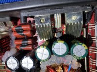
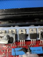
I included a picture from the PS FETs (first picture), and the output FETs (second picture).
I think the PS FETs are good, but I’m not 100% sure I tested it right. I’ve watched many videos, but they are all testing FETs out of circuit. Does it matter whether I am testing them in or out of circuit? Will I get the same results?
After removing the burned diode, I measured the resistance between B+ and Ground and it read OL. But the resistance between Ground and the Remote reads .925 mOHMs. I don’t know if that’s normal?
I definitely need to buy this tutorial that people are talking about.
I really appreciate everyone responding and helping me!
Thanks guys,
Pat
Attachments
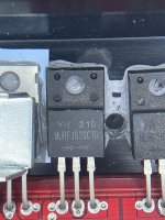
The reason that I wanted to know if the output FETs were defaced is because that would make a reliable repair more difficult.
The PS FETs aren't in the photos. The first photo is the rectifiers. They should have read 0 ohms across the outer terminals.
You will get different readings in and out of the circuit but when FETs fail, they commonly read 0 ohms and that can't be mistaken with something on the board skewing the readings.
I don't know what the remote should read but it's not shorted so that's good. The same thing applies to the PS FETs.
I’m not getting any shorted pins on the power FETs I don’t think. None of the pins read 0 ohms.
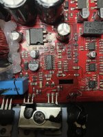
The last two pics are in response to the comment from the other gentleman about what he saw by the potentiometers, it looks like some kind of residue to me. But idk. Definitely don’t know how to test these.
Thanks guys
The last two pics are in response to the comment from the other gentleman about what he saw by the potentiometers, it looks like some kind of residue to me. But idk. Definitely don’t know how to test these.
Thanks guys
Attachments

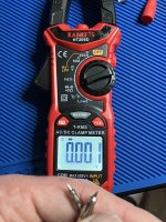
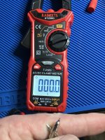
When you touch your meter probes together, what does it read on ohms and diode-check?
What make/model meter?
From here, on, whatever your meter displays for any reading (voltage, resistance, diode-check...), post the exact reading (all digits on both sides of the decimal, unless you're using something like a Keithley 2002).
What make/model meter?
From here, on, whatever your meter displays for any reading (voltage, resistance, diode-check...), post the exact reading (all digits on both sides of the decimal, unless you're using something like a Keithley 2002).
I have two meters, they’re both kinda cheap. Ones a Harbor Freight Cen-tech P98674. The other is a Kaiweets HT206D. I took pictures of the readings you’re asking for.
Attachments


The outer terminals of the rectifiers should read 0 ohms. Are you saying that you didn't read well below 1 ohm from terminal 1 to terminal 3?
When checking any 3-terminal component place the meter probes on terminals:
terminal - terminal
1-2
1-3
2-3
With the component out of the board, you should reverse the probe positions and repeat... on both resistance and diode-check to be thorough.
When checking any 3-terminal component place the meter probes on terminals:
terminal - terminal
1-2
1-3
2-3
With the component out of the board, you should reverse the probe positions and repeat... on both resistance and diode-check to be thorough.
- Home
- General Interest
- Car Audio
- Hello All! Looking for help! - protection cirtcuit on a Sundown SAEv3-1500D